Electronics Area – Electrical and Electronics Tutorials and Circuits
Welcome to Electronics Area
Electrical and Electronics Tutorials and Circuits
Recent posts
PWM – What is Pulse Width Modulation?
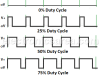
PWM (Pulse Width Modulation) is a technique used to control the width of a digital signal in order to adjust the power delivered to certain devices.
High-Speed Electronic Fuse for Solid-state Circuits
The high-speed electronic fuse circuit operates in nearly one-hundredth of a microsecond, making it faster than an ordinary fuse.
Current-limited 6 V Battery Charger
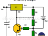
This current-limited 6V battery charger uses the well-known LM317T regulator to control the maximum current at which a 6-volt battery can be charged.
How do I test a Zener diode? – A simple method
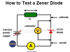
Procedure to be followed when testing Zener diodes. How to find the voltage of an unknown zener diode
Equivalent transformer circuits (power, audio, video and RF)
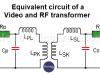
Equivalent transformer circuits (power, audio, video, and RF). Normally, in the designs and analyses where transformers are used, it is very common to use the characteristics of the transformer as if it were an ideal transformer.
Wirewound Resistor
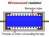
A wirewound resistor is used when the power to be dissipated is very high. A wire wound resistor is usually coated with a layer of vitreous enamel.
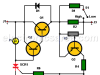
Light detector circuit using LDR (automatic night light)
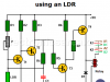
This circuit activates a lighting device through a relay when the intensity of daylight is no longer sufficient. Good for illuminating the main entrance of the house, a display case that needs to be kept lit at night, an unsafe area at night, etc.
The Decibel – Voltage Gain & Power Gain

Voltage gain and Power Gain on an Amplifier – Explanation and formulas. The decibel expresses a ratio of quantities, not a quantity itself.
Blown Fuse Indicator Circuit using one transistor
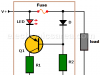
This single transistor blown fuse indicator circuit warns us by lighting a LED when there is a problem in an electrical installation protected by the fuse.
Logic Probe using NOT Gates
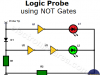
A very simple logic probe using NOT gates. The logic probe allows us to know the logic state of any point in a digital circuit. The signal to be measured is applied to the probe tip input.
Resistors in Series – The Equivalent Resistance
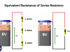
Series resistors are those that are connected in series and have the same current flowing or circulating through them
How to increase the output voltage of 78XX regulators?
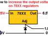
How to increase the output voltage of 78XX regulators. How to use a zener diode to boost the output voltage on a 7805, 7809, 7812, 7815, ….regulators.