Test Equipment Circuit Schematics
Test equipment Circuit Schematics
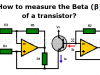
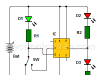
How to measure Beta of a transistor – Very easy
The beta (β) is a characteristic of each transistor. This feature is found in the NTE, ECG manuals, etc. These manuals have a minimum or approximate values of the real values. This means that we do not know the real value of the transistor.
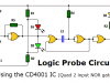
Logic Probe Circuit using NOR gates
Logic probe circuit with CD4001 IC. This circuit is implemented with CMOS IC technology and is recommended for testing circuits using the same technology
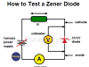
How do I test a Zener diode? – A simple method
Procedure to be followed when testing Zener diodes. How to find the voltage of an unknown zener diode
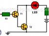
Logic Probe using two transistors
This Logic Probe is a simple circuit implemented using two NPN bipolar transistors (T1, T2) in a Darlington configuration
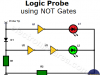
Logic Probe using NOT Gates
A very simple logic probe using NOT gates. The logic probe allows us to know the logic state of any point in a digital circuit. The signal to be measured is applied to the probe tip input.
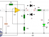
Diode Tester Circuit using 741
This diode tester circuit checks, if the diode is in good condition and also determines its polarity. To accomplish our goal, we use an 741 operational amplifier (IC1) configured as an oscillator.
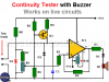
Audible Continuity Tester
This continuity tester with buzzer works on live circuits. Very important, as common continuity testers are used with the power source disconnected.
Continuity tester using 741 IC
A good application for this circuit would be to test welds made on a printed circuit board. It could also be used to test continuity of wires, connections, etc.
555 Timer Tester circuit
This 555 IC tester circuit, allows us to make sure that this integrated circuit works properly. This same test can be achieved by operating the 555 as astable multivibrator, but this test does not allow observing its operation in detail.
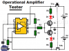
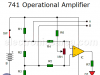
Op Amp Tester Circuit Diagram
Very simple circuit to test 741 op amp or another IC with the same pin configuration. Circuit working explanation
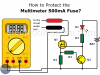
How to protect multimeter’s 500mA fuse?
A very simple circuit that protect the 500mA fuse of a multimeter, due to the high frequency that these are burned.
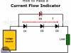
How to Make a Current Flow Indicator?
This Electric Current Flow Indicator gives a visual indication that there is a current flow. Possible applications for this small circuit may be: a battery charger, a voltage power source, etc.
In order to achieve our objective we place 3 rectifier diodes in series, which in turn are in series with the load / battery.
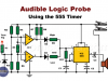
Audible Logic Probe using the 555 Timer
Many logic probes use LEDs to visually indicate the logic state of the point under test. This causes the user to have to see the point under test and the LED at the same time.
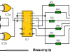
Logic Probe with 7 Segment Display
This logic probe with 7 segment display is designed with TTL technology and does not use LEDs to display the high and low logic levels found in many of the logical probes on the market. The circuit shows the capital letter “H” when there is a logical “1” or the letter “L” when there is a logical “0”.