Home / Circuits / Timer circuits /
High power pulse generator using the 555 timer
This High current pulse generator is useful in applications where the pulses given by a 555 alone do not have enough current. With the 555 timer you get an output with two voltage levels, a high and a low, but the current capacity of this IC is very limited.
If a power transistor is placed at the output, a high current delivery capacity could only be obtained when it is at high level or only at low level (it depends on the type of transistor and how it is connected).
Since what is desired is to achieve a high current capacity pulse (a power pulse) both in high and low level, a 555 timer, a transistor and a voltage regulator are used as main components. See the diagram.
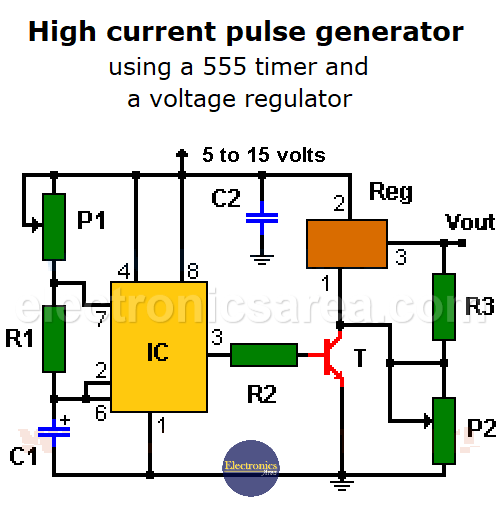
Power Pulse Generator (High Current Pulse Generator)
Output Waveform of the high current pulse generator (Vout)
From the diagram it can be seen that the minimum value of the output is 1.2 Volts (minimum voltage delivered by the regulators used) and the maximum voltage will be approximately 3 volts less than the supply voltage. The 3 volt drop is due to the voltage drop between the input (pin 2) and the output (pin 3) of the voltage regulator.
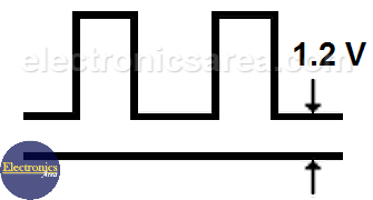 Output Waveform of High Current Pulse Generator
How the High current pulse generator works?
This diagram shows how a 555 timer configured as an astable oscillator, is connected, at its output, with a very popular variable voltage regulator, such as the LM317, LM150, LM250, LM350, which have the capacity to give voltages ranging from 1.2 volts up to 33 volts with a maximum current delivery of 3 amps (amps).
The minimum voltage at low level will be the minimum voltage obtained from the regulator, and the maximum high level will depend on the maximum voltage of the power supply that is using the circuit.
With this type of circuit, direct current lamps could be controlled directly. Power lamps that oscillate between on and off, as a danger signal on a road, is a good application.
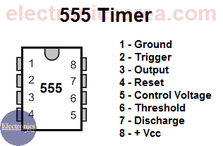
555 Timer Pin Out
Direct current motors can also be controlled. Adjusting the oscillation frequency (with the 100K resistor) can modify the motor speed.
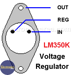
LM350K – Variable Voltage Regulator (Pinout)
Since the 555 is working as an oscillator, it will cause the transistor to continuously enter its cutoff and saturation zones. The frequency with which this is done is controlled with the 100K potentiometer, and the 10K potentiometer is used to modify the pulse width.
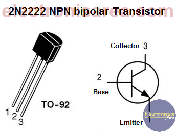
2N2222 NPN transistor pinout
Circuit component list
- 1 LM350T / LM250T / LM150T / LM317T voltage regulator. (Reg). These voltage regulators can vary in their current capacity. Choose the one that works for the application
- 1 555 timer (IC)
- 1 2N2222 NPN transistor or equivalent (T)
- 1 10K resistor (R1)
- 1 1 KΩ resistor (R2)
- 1 220 Ω resistor (R3)
- 1 100 KΩ (1/2 watt) potentiometer (P1)
- 1 10 KΩ (1/2 watt) potentiometer (P2)
- 1 0.1 uF (microfarads) capacitor (C2)
- 1 0.01 uF to 10 uF (microfarads) electrolytic capacitor (C1)
- 1 heat sink for voltage regulator
More timer Circuits
- Perfect Square Wave – Formula – Examples
- High current pulse generator
- Electronic Doorbell Circuit (555 & CD4017)
- Automatic Night Light (555 & relay)
- Sound Activated Flash trigger (555 & LM386)
- Off-Delay Timer Circuit using 555 IC
- Time Delay circuit using (Triac & 555 IC)
- 5 to 30-Minute Timer Circuit (7555 IC)
- Long Duration Timer with NOR gates
- Missing pulse detector circuit (555 timer)
- ON-OFF Switch circuit using a 555 IC (PCB)
- Event Sequencer using the 555 timer