Fire alarm circuit using thermostats and SCR
This simple fire alarm circuit using thermostats and SCR uses several thermostats in parallel for its operation. These thermostats can be as many as you want and must be placed in places where you want to sense the temperature.
Each thermostat can be regulated so that it is activated (closed) at a certain critical temperature. This critical temperature does not have to be the same for all thermostats, and depends on where they are placed.
The SCR has the function of activating the siren and / or a visual signal such as a simple 9 or 12 volt bulb, which would be placed in parallel with the siren.
How does the fire alarm circuit using thermostats work?
When the temperatures in the different thermostats are at acceptable levels, they are not active (they are open). The gate voltage (G) of the SCR (see diagram below) is at 0 volts and does not drive. As a result, the alarm does not sound.
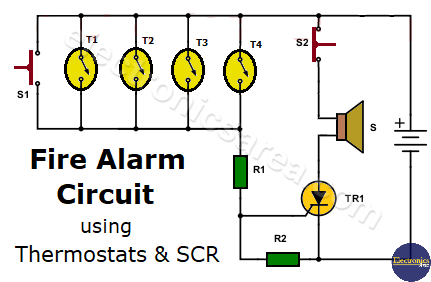
When the temperature in one or more of the thermostats rises to the critical level, they close and the supply voltage is in the upper terminal of the resistor R1. Since the resistors R1 and R2 are in series, a voltage divider is created.
The SCR gate voltage, which was previously at 0 volts, now rises to a voltage that is half the supply voltage, a voltage that is enough to trigger the SCR, makes it conduct and activates the alarm, warning of the problem.
The SCR is a device that once fired keeps conducting indefinitely. That means that even if the temperature that caused the alarm returned to normal levels, the alarm will continue to sound.

To solve this problem, the normally closed (NC) switch S2 is included. S2 is placed between the siren and V + (see diagram). When S2 is momentarily pressed, current stops flowing to the SCR and the siren, the SCR stops conducting, and the alarm stops sounding.
If for some reason, after pressing S2, some thermostat is still active, the SCR is activated and the alarm will sound again.
The normally open (NO) switch S1 is included to test the operation of the alarm circuit. The alarm can be used with a 9 or 12 volt battery or a similar voltage power source.
You may also like a Temperature Alarm using thermostats circuit.
List of fire alarm circuit components
- “n” thermostats (R1, T2, T3, … Tn)
- 1 NTE 5452 or similar SCR (thyristor) (TR1)
- 2 1K, 1/2 watt resistors (R1, R2)
- 1 normally open switch (NO) (S1)
- 1 normally closed (NC) switch (S2)
- 1 9 or 12 volts siren (S)
- 1 heat sink for TR1
Note: You can change the SCR with a higher current capacity one, but you have to take into account the triggering voltage and triggering current of the new SCR and maybe to change the R1 and R2 resistors values.


 - Thyristor")