
Power Supplies Tutorials. PS Tutorials
Home /
Power Supplies Tutorials
What is a power supply?
A power supply is an electronic device that converts alternating current (AC) voltage from the electrical grid (120/240 volts) into direct current (DC) voltage, such as 5, 9, or 12 volts. These power supplies can be classified as linear or switched-mode.
- Linear power supplies are the simplest and consist of a transformer, a rectification stage, filtering, and regulation. Their disadvantages are low efficiency and their larger size.
- Switched-mode power supplies are more complex in the process of converting AC voltage to DC voltage. Their advantages are their smaller size and higher efficiency.
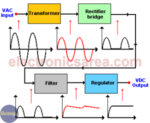
Linear power supply block diagram
Linear power supplies can also be divided into the following:
- Regulated power supplies, which are designed to maintain a virtually constant output voltage even if the input voltage changes or the load varies. These are typical 12-volt and 5-volt power supplies.
- Unregulated power supplies. These are simpler, and their output voltage can vary if the input voltage changes or if the connected load varies. They are generally older power supplies.
Below is a list of 11 tutorials on power supplies.
List of tutorials on power supplies
Transistorized Voltage Regulator (Zener & Transistor). How the Zener and transistor voltage regulator work. Circuit diagram. Example This full wave rectifier requires a center tapped transformer. This additional end on the secondary winding of the transformer divides the voltage in this winding into two equal voltages. The additional end is grounded. The half-wave rectifier rectification process. Polarization of a semiconductor diode in the forward and in the reverse direction. Input and output waveforms Transformerless power supply. This circuit is designed to connect to a specific circuit because it can only provide a maximum and minimum current. Zener Diode Voltage Regulator Circuit Design. Design method. Determination of the voltage and power of the Zener diode and of the limiting resistor Rs. Types of cells / batteries. Primary batteries (non-rechargeable): Dry, mercury, alkaline. Secondary batteries (rechargeable): Nickel-Cadmium Alkaline, Lead Electric batteries, by means of a chemical reaction, produce the following: At its negative terminal, there are a lot of electrons (negatively charged), and at its positive terminal, there is a lack of electrons (negatively charged). Voltage sources, whether batteries, generators, etc., are not ideal (perfect). A real voltage source is composed of an ideal voltage source in series with a resistance called internal resistance. Many electronic circuits need a direct current (DC) voltage source, but what we commonly find are voltage sources of alternating current (AC). In order to achieve a direct current voltage source, the alternating current input must follow a conversion process. Voltage regulators (linear, switching) provide a stable and fixed voltage output to give energy to electronics circuits from an unregulated power source Current Limiter circuit for a Power Supply using a transistor and a resistor. If the load current exceeds its maximum, an over current protection is neededTransistorized Voltage Regulator (Zener & Transistor)

Full Wave Rectifier using center tapped transformer
Half-Wave Rectifier
Transformerless Power Supply Circuit
Zener diode Voltage regulator Circuit Design
Types of Cells / Batteries
How does a battery work?
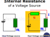
Internal Resistance of a Voltage Source. What is it?
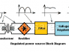
Power Supply – Block Diagram (AC – DC conversion process)
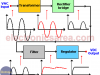
Voltage Regulators – Linear, Switching
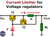
Current Limiter circuit for Power Supply using transistor & resistor
Continue using AI Cursor?Keep it onTurn Off