Power failure alarm using transformer and relay
This main power failure alarm circuit is very simple and is very useful. It can be used with electric ovens or a refrigeration system or to prevent a thief from cutting off the electrical power because it immediately warns of the problem. It also serves you to warn us when the fuses have blown.
You can connect any kind of device at the output of the circuit (relay) to call attention, such as a light, a siren, or both. See the diagram below.
Power Failure Alarm Operation
The primary winding of the 120/240 to 12 VAC transformer (T) is connected to the power lines. The transformer secondary sine wave voltage is half-wave rectified by the diode (D) and then flattened by means of an electrolytic capacitor (C).
The result is a pulsating voltage of approximately 18 VDC. This voltage constantly feeds the relay and keeps it active.
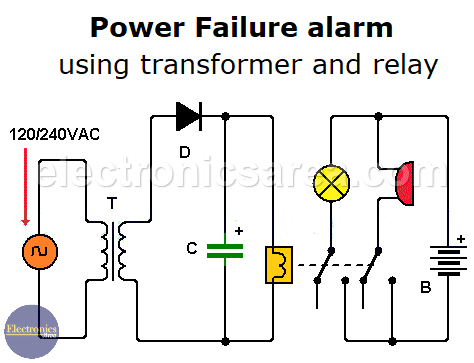
Main Power Failure alarm using transformer and relay
A relay should be a 1-pole, 2-throw device. This means that the armature moves between two possible contacts. The diagram below shows the diagram of a 1-pole, 2-shot relay.
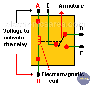
- When there is electrical power, the relay is activated and the armature is connected to one throw. (contacts D and C are active.)
- When there is no electrical power, the relay is deactivated, and the armature changes to the other throw and allows the activation of devices that give the alarm signal. (contacts C and E are active).
These devices (light, siren, etc.) can be powered with a different voltage source; it can be DC or AC. A DC source can be a 9V battery. See the first diagram.
You may also, like the main power failure alarm and battery backup circuit
List of circuits components
- 1 miniature 120/240 to 12 VAC transformer (T)
- 1 1N4001 rectifier diode or similar (D)
- 1 470 μF / 25-volt or more electrolytic capacitor (C)
- 1 12/18-volt high-impedance relay