What is the Node Analysis Method?
The node analysis method also known as the nodal analysis is widely used to solve linear resistive circuits (this method, in a slightly extended form, also applies to resistive-reactive circuits). Solving in this case means obtaining the values of the voltages in all the resistors in the circuit.
Knowing these values, it is possible to obtain other data such as: currents, powers, etc. in all the elements of the circuit. Node analysis is based on Kirchhoff’s current law:
The algebraic sum of the currents entering and leaving a node is equal to zero.
A node is defined as the point in the circuit where two or more branches meet.
The steps to follow in the node analysis method are:
- Convert all voltage sources into current sources (see Norton’s theorem).
- Choose one node to be the reference node (usually ground is chosen).
- Label all other nodes as V1, V2, V3, V4, etc.
- Create a table to form the node equations. There are 3 columns and the number of rows depends on the number of nodes (the reference node is not counted).
- The term in column A is the sum of the conductances connected to node N multiplied by VN.
- The terms in column B are the conductances connected to node N and another node X by VX (the reference node is not included as node X). There can be several terms in column B. Each of them is subtracted from the term in column A.
- The term in column C, to the right of the equals sign, is the algebraic sum of all current sources connected to node N. The source is considered positive if it supplies current to the node (to the node) and negative if the current leaves the node.
- Once the table is prepared, the system of equations is solved for each VN. It can be done by the substitution method or by the determinant method. In the end, if a value of V has a negative value, it means that the original voltage has been assumed in the opposite direction.
You may also want to read the Loop Current Method
Example of node analysis method:
Obtain the values of the voltages V1 and V2 from the following figure:
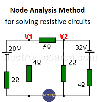 Figure 1
First, all voltage sources are transformed into current sources (Norton’s Theorem) and the first circuit is obtained (Figure # 2). Then the equivalent resistances of the parallel resistors (2 and 4 ohms in V1) and (2 and 4 ohms in V2) are calculated. (Figure #3).
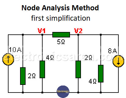 Figure 2
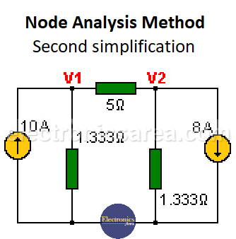 Figure 3
In node analysis, it is more convenient to use conductances instead of resistances. Each of them is transformed into its corresponding conductance value and the following circuit is obtained:
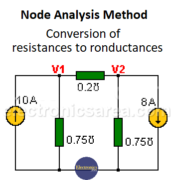
Conversion of Resistances to Conductances
The lower node (union of all resistors except the 5 ohm one) is chosen as the reference node and the other nodes V1 and V2 are labeled, as seen in the figure. The table with two rows (2 equations) is implemented since there are two nodes without taking into account the reference node.
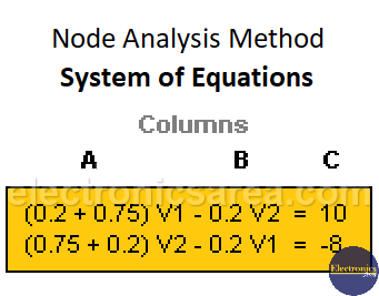
System of Equations
With the generated table, we proceed to solve the variables V1 and V2, either by the substitution method or with the help of determinants. The results are: V1 = 9.15 volts, V2 = – 6.5 volts.


