Home / Circuits / DIY Test & measuring /
Diode tester circuit using and Op. Amp.
This diode tester circuit checks, if the diode is in good condition and also determines its polarity. To accomplish our goal, we use an 741 operational amplifier (IC1) configured as an oscillator.
The oscillator use R1, R2, R3 resistors and the C1 capacitor. The oscillator output a square wave that make the D2 and D3 LEDs to turn On and OFF, showing the state of the diode under test.
How the diode tester circuit works?
The diode to be tested is placed between points A and B, as shown in the circuit diagram.
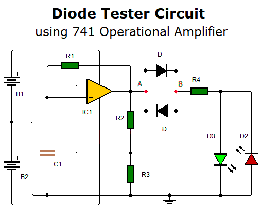
First case: When the diode under test is connected cathode to point B and anode to point A.
- When the oscillator output is at high voltage level, the diode under test must be forward biased and consequently the D3 LED should light.
- When the oscillator output is at low voltage level, the diode under test, will be polarized in reverse and as a result no LED should light.
Second case: When the diode under test is connected cathode to point A and anode to point B.
- When the oscillator output is at high level, the diode under test must be reverse biased and no LED should light.
- When the oscillator output is at low voltage level, the diode under test, will be forward biased and consequently D2 LED lights.
If the diode under test meets the above conditions, the diode is in good condition and we have determined its polarity. If not, it is damaged.
- If a LED is always on, it means that the diode under test is shorted.
- If no LED lights up, it means that the diode under test is open.
This circuit is powered by a dual polarity power supply. You can also power up the circuit with two 9V batteries, as shown in the circuit diagram. Resistor R4 is included in series with LED to limit the current passing through them.
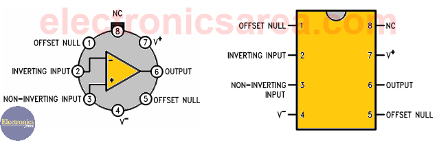
741 Operational Amplifier Pinout
Diode tester circuit components list
- 1 741 operational amplifier (IC1)
- 2 1M resistors (R2, R3)
- 1 6.8K resistor (R1)
- 1 470 ohm resistor (R4)
- 1 100 uF capacitor (C1)
- 1 red LED (D2)
- 1 green LED (D3)
- 2 9V batteries (B1, B2)
- 1 switch
More DIY Test & Measurement Circuits
- How do I test a Zener diode? – A simple method
- Diode tester circuit with 741
- Audible continuity tester
- Continuity tester using 741 IC
- 555 Timer tester circuit
- Op Amp Tester circuit diagram
- How to protect the 500mA fuse of a multimeter?
- How to make a current flow indicator?
- How to measure Beta of a transistor?
- Logic Probe using NOT gates
- Acoustic Logic Probe using the 555 Timer
- Logic Probe with 7 segment display
- Logic Probe circuit using CD4001 IC
- Logic Probe using two transistors


