Electronics Area – Electrical and Electronics Tutorials and Circuits
Welcome to Electronics Area
Electrical and Electronics Tutorials and Circuits
Recent posts
Mesh Current Method – Steps to follow – Example
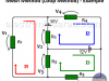
The mesh current method is very useful for finding all the currents in a network. This method, a little more advanced, is also applied to circuits where there are resistances and reactances.
Emergency Lighting Circuit with LEDs and Rechargeable Battery
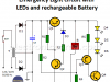
This circuit is very interesting because, unlike emergency lighting circuits that use incandescent bulbs, it uses high-efficiency LEDs.
Node Analysis Method – Steps – Example
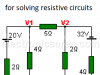
The node analysis method also known as the nodal analysis is widely used to solve linear resistive circuits (this method, in a slightly extended form, also applies to resistive-reactive circuits)
Voltage Divider – Voltage Divider Formula
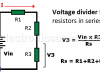
The voltage divider is a circuit that allows us to obtain an output voltage less than the input voltage. The output voltage is normally obtained across ground and the resistor connected to it, but it could be across any of the other resistors.
Maximum Power Transfer Theorem Explanation
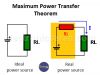
What does the Maximum Power Transfer Theorem say? “The maximum power transfer to the load is obtained when the load resistance RL is equal to the internal resistance of the…
Karnaugh Map (K-map) – How to simplify Boolean functions
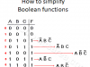
The Karnaugh map (K-map) is a widely used tool for simplifying logic circuits. When you have a logical function with its truth table, and you want to implement this function in the simplest and most economical way, this method is used.
Energy-saving Flashing Pilot Light
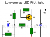
This Energy-saving Flashing Pilot Light Circuit is intended to give us a visual warning that we have electronic equipment turned on. This is especially important on equipment that uses batteries.
Electronic Filters – Low-Pass, High Pass, Band Pass
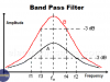
Electronic Filters – Filters are networks that allow or block the passage of a specific group of frequencies (frequency band)
Perfect Square Wave with 555 – Formula – Examples
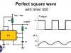
Perfect Square Wave with 555 – A simple circuit that uses the 555 timer to produce a stable perfect square wave. Formula, examples.
Audio Splitter Circuit Diagram – 1 Input – 4 Outputs
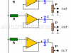
This 1 Input – 4 Outputs Stereo Audio Splitter has a single input and 4 independent outputs, each amplified with an operational amplifier configured as a voltage follower.
Light sensitive alarm using LDR
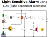
This alarm activates when the illumination level changes from almost total darkness to a moderately high illumination level. When this happens the alarm is locked and the alarm signal, be it a light or a sound, remains active.
Off-Delay Timer Circuit using 555 IC
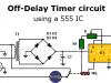
This off-delay timer is ideal when we want to schedule the automatic shutdown of a device after a predetermined time, using the well known 555 IC