Home / Semiconductors /
Why is there a diode connected in parallel to a relay coil?
The purpose of a diode in parallel to a relay coil (flywheel diode or freewheeling diode) is to avoid damaging some nearby components sensitive to high voltage. This voltage is generated in the coil when the current flow is interrupted.
The purpose of the diode is to allow the current flowing through the coil to continue circulating when the relay is deactivated.
How does a diode connected in parallel to a relay coil work?
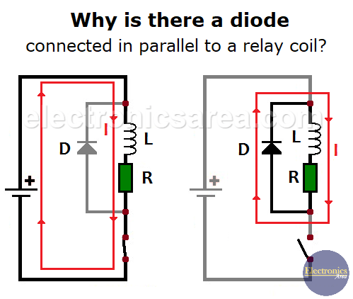
1. When the relay is active, a current flows through the coil. No current passes through the diode because it is inversely polarized.
2. When the relay is deactivated, the coil tries to maintain the current flow. As there is no way for the current to circulate, a diode is placed parallel to the coil. In this way, the current circulates through the diode, and voltage peaks are prevented from damaging other components of the circuit.
The coils have a very interesting feature. If the current flow stops abruptly, the voltage in the coil changes polarity so that the current continues to circulate. (This takes a limited time).
What are the electrical characteristics that the diode should have?
The diode must withstand the supply voltage. If the relay is connected to a 24V power source, the diode must support 24 volts plus a safety margin.
The diode must withstand the amount of current that passes through the relay coil when it is active. This current passes through the diode when the relay is deactivated.
Example of operation of a diode connected in parallel to a relay coil.
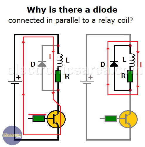
We are going to activate a 12-volt relay by means of the NPN 2N3904 transistor. Operation of the diode in parallel with a relay when activated by a transistor (relay is partially shown)
When the relay is energized
When the relay is energized, the transistor is in the saturation region, and there is a voltage of 0.1 volts between the collector-emitter terminals. (transistor is saturated). The current (I) flowing through the coil L is limited by its internal resistance (R).
Knowing that the supply voltage is 12V and that the collector-emitter voltage of the VCE transistor is 0.1 V, the relay has 12V – 0.1V = 11.9V between its terminals.
When the relay is de-energized
The relay begins the process of deactivation when the transistor passes to its cutoff region (the transistor does not conduct), and there is 0.6 V at the terminals of the diode (D).
At this moment the collector voltage of the transistor is 12V + 0.6V = 12.6V, while the current (I) in the coil passes through the diode.
When the remaining current has passed through the diode, the collector voltage of the transistor is again 12V, and the diode is reverse-polarized. (The relay is not activated).
You may be interested in the light detector circuit using transistors and a relay circuit.


