Digital Electronics
Home /
Digital Electronics
Digital electronics is a field of electronics that involves the study of digital signals and electronic circuits that are used to process and control digital signals. By contrast, in analog electronics, where information is represented by a continuously varying voltage, digital signals are represented by two discrete voltages, or logic levels.

What are logical levels in digital electronics?
In digital circuits and components such as the logic gate, it is common to say that we have a logic “high” or a logic “low” at the input or output of a circuit. If we have a “high” level we say that it is a “1” and if we have a “low” level we say that it is a “0”.
If we were using a TTL IC running on +5 volts, the “1” would be a voltage level of +5 volts and the “0” would be a voltage level of 0 volts. This is the ideal case in digital circuits.
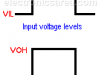
TTL, CMOS and HC logic levels (voltage levels)
In the real world, these values are different. Digital integrated circuits operate with input and output values that vary depending on the technology of the integrated circuit.
In the TTL family, a logic “0” means the voltage level is between 0 and 0.8 volts and a logic “1” means the voltage level is between 2 and 5 volts.
In CMOS technology, a logic “0” means the voltage level is between 0 and 1.5 volts and a logic “1” means the voltage level is between 3.5 and 5 volts.
What is a logic circuit in digital electronics?
A logic circuit uses two logic levels to transfer information. A logic high level or “1” and a logic low level or “0”. Logic circuits are made of digital elements such as AND gate, OR gate, NOT gate, and combinations of them.
These combinations give way to other types of digital electronic components, such as logic gates, flip-flops, microprocessors, memories, among others.
Modern digital electronics are used to perform many functions. Although digital electronic circuits may seem very complex, they are actually built with many very simple circuits.
Digital Electronics Tutorials
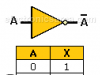
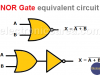
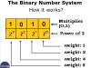
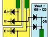
The NOT gate is a logic gate that has only one input and one output. The output logic level is the opposite of the input logic level The NOR gate—truth table and equivalent circuit. It can be implemented with the concatenation of an OR gate and a NOT gate. The Gray code is an unweighted code. Between any combination of digits and the next one, there is only a difference of one digit. Gray code Table The binary number system only needs two (2) digits: “0” and “1”. How to make the decimal to binary and binary to decimal conversion. Truth Table is used to simplify boolean equations obtained from digital circuits. The truth tables can have many columns, but all tables operate in the same way. Diode Logic OR gate (wired OR connection) and Diode Logic AND gate (wired AND connection). Diode Logic uses the fact that diodes conduct only in one direction. (they behave like switches) In order to share information in digital format, it is common to use a binary or hexadecimal representations (BCD Code). There are other methods to represent this information and one of them is the BCD code. Difference between Analog and Digital. Digital refers to a discrete quantity. Analog refers to the quantities that vary with time on an ongoing basis. A Logic circuit uses two logic levels to transfer the information. A high logic level or “1” and a low logic level or “0”. The Logic circuits are made of digital elements such as the AND gate, the OR gate, the NOT gate and a combinations of them. In digital circuits, it is common to say that we have a “high or a “low” logic level at the input or output of a circuit. If we have a “high” level we say it is a “1” and if we have a “low” level we say that it is a “0”. Boolean Algebra is a tool to reduce logical expressions. It is the mathematics of logical expressions, which was presented by George Boole in 1854. The Karnaugh map (K-map) is a widely used tool for simplifying logic circuits. When you have a logical function with its truth table, and you want to implement this function in the simplest and most economical way, this method is used. The hexadecimal numbering system (base-16). This numbering system is mainly used to simplify the representation of binary numbers and for the digital handling of colors. Aiken BCD code is similar to the natural BCD code, but with “weights” or “values” distributed differently. The Excess 3 Code is obtained by adding “3” to each combination of the natural BCD code. The logic AND gate is one of the simplest gates in Digital Electronics. The output of an AND gate is true (“1”) only when all inputs are true (“1”). If one or more inputs are false (“0”), then the output is false (“0”). The NAND gate, also called a universal gate, is a gate that produces a logic “0” output only when all logic inputs are “1”. The NAND gate truth table The logic Or gate is one of the simplest digital logic gates. The output of this gate is “High”, when one or all of its inputs are “High”. We can also say that, the output of an OR gate is “Low” only when all gate inputs are “Low”. In digital electronics there are special gates. One of them is the XOR logic gate or exclusive OR gate. Equivalent XOR Logic Gate using common logic gates This circuit simulates the operation of a NAND gate with two or more inputs. (There is one diode for each input. D1, D2, …) A combinational circuit is a circuit where the output depends only on the combination of the inputs at the time we are testing the output A sequential circuit is a circuit where there are one or more feed backs from one or more outputs. The new output depend on the inputs and the last output The JK Flip-Flop is a sequential device with 3 inputs (J, K, CLK (clock signal)) and 2 outputs (Q and Q’). J and K are control inputs. The binary decoder is a device that accepts a digital input (in binary form) and it activates one of its outputs. This device has several outputs, and the one that is activated is chosen by the code applied to the inputs.NOT Gate (Inverter) – Symbol, Truth Table
NOR Gate – NOR gate truth Table – Equivalent circuit
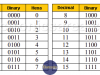
Gray code – Gray code Table

Binary Number System – Decimal to Binary & vice versa – Videos
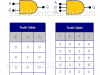
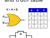
Truth Table – What is it? – Definition – Examples

OR and AND logic gates made with diodes
BCD code: binary-coded decimal.

What’s the Difference between Analog and Digital?
What is a Logic Circuit?
Digital Logic Levels (hight, low, 1, 0)
Boolean Algebra – Introduction and Rules
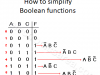
Karnaugh Map (K-map) – How to simplify Boolean functions
Hexadecimal Numbering System
Aiken code – Excess 3 code
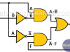
Logic AND Gate – AND Truth Table
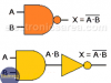
NAND Gate – The Universal Gate
Logic OR gate – Symbol & Truth Table
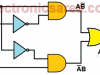
XOR Logic Gate
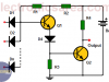
How to build a NAND Gate with Transistors & Diodes?
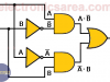
Combinational Circuit
Sequential Circuit – Digital Logic
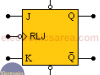
JK Flip-Flop
What is a Binary Decoder?