Jun 252024
Home / Circuits / DIY Test & measuring /
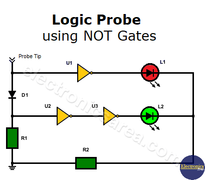
Logic Probe using NOT Gates (Inverters)
This very simple logic probe using NOT gates (inverter gates) consists of three NOT gates, a rectifier diode, two LEDs and two resistors. The logic probe allows us to know the logic state of any point in a digital circuit. The signal to be measured is applied to the probe tip input.
How does the logic probe work?
When the input signal is “high” (logic 1):
- The top NOT gate inverts the signal and the red LED is off.
- The diode is directly polarized, the signal is inverted twice by the two cascaded NOT gates, and the green LED is lit.
When the input signal is “low” (logic 0):
- The upper NOT gate inverts the input signal and the red LED lights.
- The diode is reverse-polarized and does not conduct. As a result, there is a “logical low” at the diode’s anode. This logical low is inverted twice, and the green LED does not light up.
The resistor R2 limits the current flowing through both LEDs (green and red). To implement the circuit, a TTL SN7404 integrated circuit (6 NOT gates in a single IC) is required.
Notes:
- A 5-Volt power source powers this circuit and can only be used to test digital circuits manufactured with TTL integrated circuits.
- The ground (0 volt) connection of the circuit under test and the 0 volt connection of the digital probe must be the same.
List of components for the logic probe circuit
- 1 TTL SN7404 integrated circuit (6 inverters or NOT gates) (U1, U2, U3)
- 1 1N4001 or similar rectifier diode (D1)
- 2 LEDs (red, green) (L1, L2)
- 1 220 ohms, 1/4 watt resistor (R2)
- 1 10K, 1/4 watt resistor (R1)
You may be interested in:
- Logic Probe with 7 segment display
- Logic Probe circuit using CD4001 IC
- Logic Probe using two transistors
More DIY Test & Measurement Circuits
- How do I test a Zener diode? – A simple method
- Diode tester circuit with 741
- Audible continuity tester
- Continuity tester using 741 IC
- 555 Timer tester circuit
- Op Amp Tester circuit diagram
- How to protect the 500mA fuse of a multimeter?
- How to make a current flow indicator?
- How to measure Beta of a transistor?
- Logic Probe using NOT gates
- Acoustic Logic Probe using the 555 Timer
- Logic Probe with 7 segment display
- Logic Probe circuit using CD4001 IC
- Logic Probe using two transistors


