Alternating Current (AC)
Home /
Alternating Current (AC) Tutorials
Power Factor (PF) Definition and Formulas
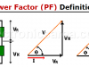
Power factor is the ratio between the energy that is converted into work and the electrical energy consumed in a circuit or device
Nonlinear Amplitude Control of a Sinusoidal Oscillator
Control of a sinusoidal oscillator is done in 2 phases: a linear method based in the frequency domain and a non-linear method using non linear mechanisms
Wien-bridge Oscillator with Op Amp
The Wien-bridge oscillator, consists of an Operational Amplifier (OA) in a non-inverting configuration with gain 1+R2/R1 and a RC feedback network
Phase Shift Oscillator
The phase shift oscillator is a negative gain amplifier (-K) and a feedback network consisting of a third order RC section in cascade
LC Oscillator – Inductance – Capacitance Oscillator
LC oscillator: Inductance – Capacitance Oscillator A simple oscillator can be built with an amplifier stage and an inductive-capacitive network (LC) to provide an offset of -180°. The oscillation frequency can be freely adjusted…
Crystal Oscillators – Piezoelectric Oscillator. Equivalente circuit
The Crystal Oscillators (Piezoelectric Oscillator) A quartz crystal has a property called: piezoelectric effect. This effect causes, by applying a mechanical pressure on the surface of the crystal, that a voltage is developed…
Sinusoidal oscillators – Basic principles
Sinusoidal oscillators play an important role in electronic systems that use harmonic signals. Despite that, in many instances are known as linear oscillators
Sinusoidal oscillator (basic structure)
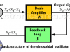
The sinusoidal oscillator basic structure consists of an amplifier (A) and a selective frequency network (ß) connected in a positive feedback loop
What is an Alternating Current?
The difference between an alternating current and a direct current is that a direct current only flows in one direction. Alternating current circulates in one direction, then the opposite direction, and repeats this process continuously.
What is a radian? – Angular frequency (video)
What is a radian?
The radian is the angle that cover the portion of the circumference which is equal to the length of the radius of the circle
The Decibel – Voltage Gain & Power Gain

Voltage gain and Power Gain on an Amplifier – Explanation and formulas. The decibel expresses a ratio of quantities, not a quantity itself.
Power in AC Circuit
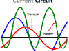
Electric power. Electrical power on a circuit with reactive load (reactance). How to obtain the current in a circuit having resistance and reactance.
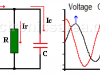
Series RC circuit connected to an AC voltage
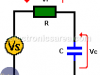
In a series RC circuit, the current through the resistor and the capacitor is the same. The voltage VS is equal to the phasor addition of the voltage drop across the resistor (Vr) and the voltage drop across the capacitor (Vc).
Resonance in an RLC Circuit
Resonance in RLC Circuits is a special condition for parallel and series RLC circuits, when capacitive reactance and inductive reactance have the same magnitude and cancel each other. This only happens at frequency fo.
Impedance (Z) = (Resistance + Reactance)
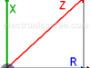
Impedance (Z) shows the opposition to the flow of direct or alternating current. Impedance is the vector addition of resistance (R) and reactance (X).
Push – Pull Amplifier – Push – Pull Amplifier Operation
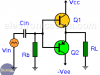
Push – Pull Amplifier
A Push – Pull amplifier is called that way, because it uses 2 groups of transistors and only one works at a time. One group pushes in one direction while the other pulls in another direction. Each group is responsible for amplifying a single phase of the input wave.
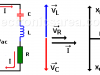
Parallel RC circuit
Parallel RC circuit
Voltage, Currents, Phasor diagram & Impedance. Voltage is the same on the capacitor and resistor. Current is ahead of the voltage in the capacitor