Home / Circuits / LED Circuits /
Emergency lighting circuit with LEDs
This Emergency Lighting Circuit with LEDs and rechargeable battery is very interesting because, unlike emergency lighting circuits that use incandescent bulbs, it uses high-efficiency LEDs.
A circuit with these characteristics provides a reliable source of light that lasts many times longer than traditional incandescent emergency lighting systems and consumes much less energy.
How does the emergency lighting circuit with LEDs work?
- The diagram shows a circuit that consists of two parts:
- The first part of the circuit is responsible for charging the battery when there is power from the wall outlet.
The second part of the circuit is responsible for activating the LEDs when there is no external power.
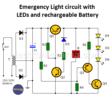
When power is available from the wall outlet, the battery is charged by transistor Q1. Q1 is polarized and conducts the current that passes through resistor R1.
The Zener diode is used to protect the battery from overcharging. The sum of the voltage across the Zener diode plus the base-emitter drop of transistor Q1 (0.65V) is the maximum voltage the battery can be charged to before the system shuts off the charge.
When this voltage is reached, the Zener diode begins to conduct by biasing transistor Q2, which removes the bias current from transistor Q1. This causes Q1 to stop conducting and the battery charging stops.
As long as there is power from the outlet, the voltage divider created by resistors R2 and R4 will not allow transistors Q3 and Q4 to be biased, preventing the LEDs from turning on.
When there is no power in the outlet, the voltage at the junction of resistors R2 and R4 decreases, polarizing transistors Q3 and Q4 and turning on the LEDs. The situation is reversed when the power returns.
The transformer (T), diodes D1 and D2, and electrolytic capacitor C1 form the unregulated voltage source from which the circuit operates.
Switch SW1 is used to test system operation. When SW1 opens, the LEDs should light. A normally closed (NC) momentary switch may work well. The battery to be charged must be a 12V lead acid battery.
List of circuit components
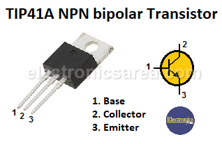
- 2 NPN bipolar transistors TIP 41 A or equivalent (Q1, Q4)
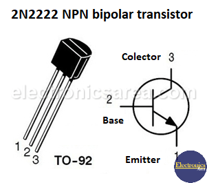
- 1 NPN bipolar transistor 2N2222 or equivalent (Q2)
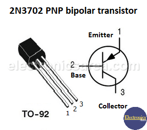
- 1 PNP bipolar transistor 2N3702 or equivalent (Q3)
- 1 Zener diode 12V, 1/2 watt (D3)
- 2 Diodes 1N4004 or similar (D1, D2)
- 3 high efficiency white LEDs (D4, D5, D6)
- 1 x 560 Ohm resistor (R1)
- 1 x 220 Ohm resistor (R2)
- 1 x 1K resistor (R3)
- 1 x 10K resistor (R4)
- 1 x 510 Ohm resistor (R5)
- 1 x 1000 uF (microfarad) capacitor / 35 V or more (C1)
- 1 Transformer 120/240 V to 18 V, 1 A. with center tap (T)
- 1 system test switch (SW1)
Important Note: Since transistors Q1 and Q4 are power transistors, several arrays of LEDs similar to those that make up LEDs D4, D5, and D6 can be connected in parallel to increase the illumination provided by the circuit.
More LED circuits
- Emergency lighting circuit with LEDs
- Automatic night light circuit with one LED (PCB)
- Bike flashing LED lights circuit
- Flashing LEDs circuit for pedestrians
- Two-way traffic light circuit
- LED sequencer using 4017 decade Counter (LED Chaser)
- Light push button circuit with time delay
- Energy-saving flashing pilot light
- LED connected to 120/240 VAC
- Police style strobe light circuit
")


