Humidity sensor circuit using the 555 timer
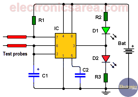
This simple humidity sensor circuit shows us the humidity level that the land under test has. To achieve the goal, a couple of probes are used. These probes are placed as shown on the diagram, with their ends buried in the ground to be tested.
The circuit uses two LEDs, which alternate their illumination at a rate that depends on the degree of the soil moisture. This is very useful to know when we need to water the plants. The two extreme cases are
- When the ground is dry, only one LED lights up
- When the ground is wet, LEDs light up alternatively, and the frequency depends on the humidity level of the soil.
How does the humidity sensor circuit work?
This humidity sensor circuit uses the 555 integrated circuit (timer). The 555 is configured as an astable multivibrator, and for the circuit to oscillate, a capacitor (C1) and two resistors are needed.
- R1 resistor: located between the 555 pin 7 and the positive terminal of the battery, as shown in the diagram.
- R4 resistor: This is not a real resistor, and it is not shown in the diagram, but in this case is replaced by the resistance of the ground under test. (resistance obtained using the probes).
555 timer pinout description
Depending on the moisture of the ground, its resistance (R4) will vary, and hence the oscillation frequency of the 555 timer. This frequency is displayed on LEDs (D1, D2). LEDs can be the same color, but in this case we use one green LED and one red LED to achieve a more noticeable display.
This circuit becomes portable if you use a 9-volt battery.
List of circuit components for the humidity sensor circuit
- 1 555 Timer (CI)
- 3 1K resistors (R1, R2, R3)
- 1 0.1 uF (microfarad) capacitor (C2)
- 1 10uF electrolytic capacitor (C1)
- 2 LEDs (1 red, 1 green) (D1, D2)
- 1 9-volt battery.
More Detector Circuits
- Light detector circuit using LDR (automatic night light)
- How to make a Light Sensitive Sound Generator Circuit?
- Light activated switch circuit with LDR and Op Amp
- Light Operated Relay Circuit using LDR / Photoresistor
- Twilight Switch Circuit
- Dark detector circuit using LDR and relay
- Darkness detector circuit with audio output using 555
- Temperature Gauge Circuit Using LM324 (PCB)
- Temperature to Voltage Converter using Thermistor (PCB)
- Rain Detector using two Transistors
- 2 LED Temperature Change Indicator with LM35 & 741
- Lie Detector Circuit Using Two Transistors
- Humidity sensor circuit using the 555 timer
- Blown Fuse Indicator Circuit using one transistor
- Electronic sound control Circuit (applause)
- Photodiode Amplifier Circuit – Current-to-Voltage Converter


In the diagram of humidity sensor, R2 is clearly shown whereas it is mentioned that R2 is not shown! . Please clarify this.
Hi Alex
I already made the corrections to the article, I hope it is understood well now, R4 is the resistance of the ground under test.
Thank You. Regards