Electronics Area – Electrical and Electronics Tutorials and Circuits
Welcome to Electronics Area
Electrical and Electronics Tutorials and Circuits
Recent posts
Dielectric Constant & Capacitors (Table)

What is the Dielectric constant / Relative Permittivity? The dielectric constant is the ratio of the permittivity of a substance to the permittivity of free space. It is a dimensionless physical constant
Binary Number System – Decimal to Binary & vice versa – Videos
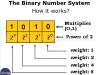
The binary number system only needs two (2) digits: “0” and “1”. How to make the decimal to binary and binary to decimal conversion.
MOSFET Transistors – NMOS, PMOS
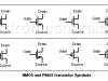
MOSFET transistors, or Metal Oxide-Semiconductor (MOS), are field effect devices that use the electric field to create a conduction channel. MOSFET transistors are more important than JFETs because almost all integrated circuits are built with MOS technology.
LM317 Variable Voltage Regulator Tutorial
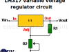
LM317 characteristics. How the voltage regulator circuit works: Regulator circuit operation improvement
Adding a Tweeter to a Speaker
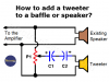
How to add a tweeter to a speaker. Very simple circuit, using only one potentiometer and two capacitors, very easy to install.
5 to 30 Minute Timer Circuit using 7555 IC
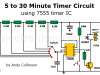
This 5 to 30-minute timer circuit achieves times ranging from 5–30 minutes using the 7555 integrated circuit (CMOS version of the popular 555 timer).
Coulomb’s Law – Electrostatic Force – Formula – Example

Coulomb’s Law—Electrostatic Force: Formula and example. Learn how to calculate the electrostatic force between 2 electric charges using Coulomb’s Law.
Structure of Matter: The Bohr Atom and the Electricity

Structure of Matter: The Bohr Atom and Electricity. The atom, the electron. Positive and negative ions. How free valence electrons become electricity
Electric Field: Lines of Force and Electric Field Unit
If the electric field at a given point is known, the electrostatic force on a charge Q at that point can be found. If a charge Q is subject to an electrostatic force, an electric field exists.
Gray code – Gray code Table

The Gray code is an unweighted code. Between any combination of digits and the next one, there is only a difference of one digit. Gray code Table
Voltage Drop Alarm Circuit: Useful for PS testing
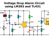
This voltage drop alarm is very useful for power supply monitoring or testing. It activates a buzzer when the test voltage drops below a reference voltage.
Surge Protection Circuit (Voltage Delay Circuit)
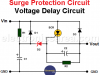
This surge protection circuit is placed between the DC voltage source and the circuit that you want to power. This circuit delays the voltage given by the power source and allows the voltage to be applied to the circuit or device a few moments later.