1 Input – 4 Outputs Stereo Audio Splitter
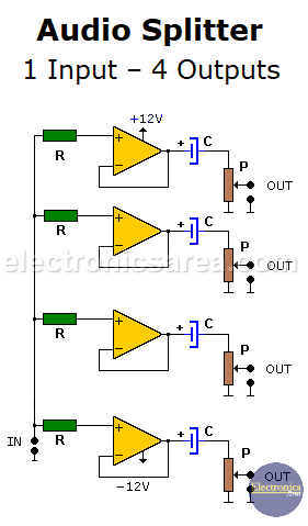
This 1 Input – 4 Outputs Stereo Audio Splitter has a single input and 4 independent outputs, each amplified with an operational amplifier configured as a voltage follower. Each operational amplifier (Op Amp) has the advantage of its high input impedance and low output impedance, thus avoiding distortion in sound.
The output electrolytic capacitors are used to prevent the continuous current component from the output of the operational amplifier from being transferred to the load. A control potentiometer is used to vary the output level of the audio signal, in each of the 4 outputs (volume).
In order to build a complete stereo system, you must make two circuits equal to the following diagram.
List of components of the Audio Splitter
- 2 LM324 or TL084 ICs (4 operational amplifiers in a single package)
- 8 100k resistors (R)
- 8 1uF / 25 volt electrolytic capacitors (C)
- 8 50K potentiometers (P)
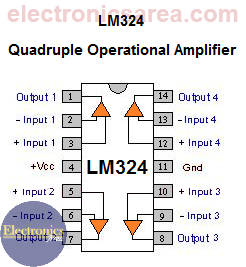
LM324 Quadruple Operational Amplifier Pin out
You may be interested in adding a tweeter to your speaker.
To power the circuit, you need a dual polarity output power supply (+/- 12V). +12V must be connected to Pin 4, and -12V must be connected to Pin 11 of the LM324. See the above image.
More Audio Circuits
- 2 watt audio amplifier with the TDA2822M IC
- 6 watt audio amplifier with TDA2613 (Hi-Fi)
- 400 watt stereo amplifier with STK4050
- 4-channel audio mixer using LM3900 IC
- Microphone mixer using operational amplifiers
- 6 LED VU meter using a single transistor
- Audio splitter – 1 Input – 4 Outputs
- Audio level indicator using LM339
- 8 LED VU meter using LM324 IC
- Music box using a CD4017 and Two 555
- Metronome with adjustable BPM
- Tone generator using two 555 timers
- How to add a tweeter to a baffle or speaker
- Guitar Synthesizer using CD4046


where to connect -12v supply in the ground pin #10?
Hello Yhen
+12V must be connected to Pin 4 and -12V must be connected to Pin 11 of the LM324
Regards
can i use resistors instead of a potentiometer?
Hello.
Yes, you can, but you won’t have a way to control the volume of the amplifier output. I think it is better to leave the circuit as it is and set the volume to the desired level.
Hope this help you.
Why do you list 8 of everyhting and only show 4 of each in the circuit diagram?
Hi Richard
You need 2 sets of audio splitters to get a complete stereo system.
Greetings