Home / Circuits / Power Supply /
12 to 5 volt converter circuit (for cars)
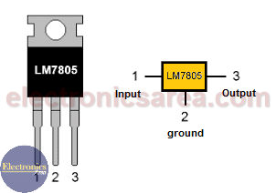
This 12 to 5 volt converter circuit is very useful. It can be used to connect 5 volt electronic devices to a 12 volt battery. (Automotive lead-acid batteries can be up to 13.5 volts). When a 5V regulator such as the LM7805 is used, the maximum current it can deliver is 1 Amp.
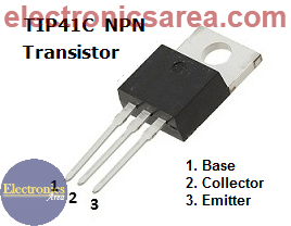
This current may not be enough for some of the devices we want to connect. It may also be insufficient if we connect 2 or more devices at the same time. To solve this problem, we will use a transistor to increase the output current.
How does the 12 to 5 volt converter circuit work?
This circuit can supply enough current using the 5 volt regulator and a transistor (Q1) as shown in the figure. Capacitors C1 and C3 are used to flatten the voltage at the input and output of the regulator. Capacitors C2 and C4 are used to filter any noise generated by the vehicle’s electrical system.
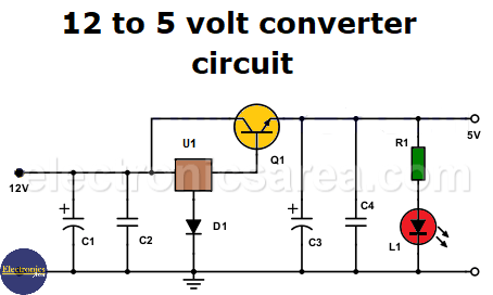
This circuit has the disadvantage of a base-emitter voltage drop (Vbe) of 0.6 or 0.7 volts, resulting in an output voltage of 4.3 or 4.4 volts. This voltage is different from the required 5 volts. Therefore, a diode is connected to the GND pin of the voltage regulator to compensate for this voltage drop.
A red LED indicates that the regulator is active. R1 is the current limiting resistor.
You may be interested in a 12 to 9 volt converter that uses a zener diode instead of a voltage regulator.
12 to 5 Volt Converter Circuit Component List
- 1 LM7805 voltage regulator IC (U1)
- 1 NPN TIP41, 2A / 50V or similar bipolar transistor (Q1)
- 1 1000 uF (microfarad), 35V electrolytic capacitor (C1)
- 1 100 uF, 35V electrolytic capacitor (C3)
- 1 0.1 uF, 50 V ceramic capacitor (C2)
- 1 0.01 uF 50V Ceramic Capacitor (C4)
- 1 1N4007 1A / 1000V diode or equivalent (D1)
- 1 Red LED (L)
- 1 330 ohm, 1/4 watt resistor (R1)
- 1 Heat sink for transistor Q1
More Power Supply Circuits
- 9V Power Supply circuit (Zener and Transistor)
- 12V Power Supply Circuit (1A)
- Op-Amp–Based 12V Power Supply (Zener and 741)
- 12 volt Power Supply using 7805 regulator
- 15V Power ON delay circuit
- 12 volt to 5 volt Converter Circuit
- 12V to -12V converter circuit using 555
- 12V to 9V Converter Circuit Diagram (PCB)
- 12V to 24V Converter Circuit
- 4 Amp Variable Power Supply Using the LM317
- LM317 4A Variable Power Supply (3 LM317 IC)
- LM350 Voltage Regulator circuit (Variable Power Supply)
- 20A Variable Power Supply (LM317)
- LM338 variable Voltage Regulator (5A)
- Mini variable Power supply circuit (0-30V, 1A)
- 7805 variable voltage regulator circuit (7805 and 741)
- Dual polarity Variable Power Supply (+15V / -15V) max
- Voltage Spike protection Circuit (Voltage Delay Circuit)
- Voltage Regulator circuit (Transistor - Zener)
- Power Supply Dummy load
- Joule Thief Circuit with no Toroid Coil
- 12V to 120 / 220 VAC inverter for fluorescent lamps


