Home / Circuits / Power Supply /
Surge Protection Circuit (Voltage Delay Circuit)
The surge protection circuit is placed between the DC voltage source and the circuit that you want to power.
When to use this circuit?
1. To delay the applied voltage
The circuit delays the voltage given by the power source and allows the voltage to be applied to the circuit or device a few moments later.
The delay time formula:
It is necessary to clarify that the delay that can be obtained with this circuit is small, and it is not exact. The formula for the delay time is approximately T = R1 x C1 (R in ohms and C in farads). A longer time is achieved with a larger electrolytic capacitor (C1).
2. To prevent a peak voltage
This circuit is also useful to prevent a peak voltage from reaching the circuit to be powered. This could happen when:
- We turn on the switch of the power supply when we plug in an electronic device connected to our voltage source.
- Electric power returns after a power outage. Sometimes the voltage is higher than normal.
- Another possible application is to prevent two or more circuits from being powered on simultaneously.
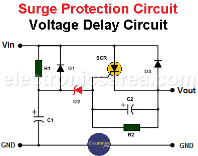
Surge Protection Circuit (Voltage Delay Circuit)
How does the voltage delay circuit work?
When the voltage of the power supply is applied to the input “In” (Vin), it does not go through immediately to the output terminal (Vout), because the diode D3, which is polarized in reverse, does not allow the passage of the current to the load.
The current starts flowing through the RC circuit (R1 and C1), and capacitor C1 begins to charge, so the voltage at its positive terminal increases.
When the capacitor voltage is equal to the addition of the zener diode voltage and the thyristor’s trigger voltage, the SCR goes into conduction and allows the passage of current from the “in” terminal to the “out” terminal.
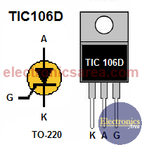
SCR TIC106D Pinout
The voltage of the zener diode must be half the voltage of the input (vin), and the amount of current that this circuit allows passing depends on the type of thyristor that is chosen. Using the SCR of the diagram, the current is 5 amps.
Resistor R2 and capacitor C2 prevent false triggering of the SCR.
List of circuit components
- 1 x TIC106D or similar thyristor (SCR)
- 2 x 1N4001 or similar diodes (D1, D3)
- 2 x 100K resistors (R1, R2)
- 1 x 22 μF electrolytic capacitor (C1)
- 1 x 1 uF electrolytic capacitor (C2)
- 1 x 6-volt, 1/2-watt zener diode (D2)
- 1 x heatsink for the SCR
C1 and C2 voltages depend on the power source. A safe value could be 50 volts or more.
You may be interested in a low-voltage alarm circuit.
More Power Supply Circuits
- 9V Power Supply circuit (Zener and Transistor)
- 12V Power Supply Circuit (1A)
- Op-Amp–Based 12V Power Supply (Zener and 741)
- 12 volt Power Supply using 7805 regulator
- 15V Power ON delay circuit
- 12 volt to 5 volt Converter Circuit
- 12V to -12V converter circuit using 555
- 12V to 9V Converter Circuit Diagram (PCB)
- 12V to 24V Converter Circuit
- 4 Amp Variable Power Supply Using the LM317
- LM317 4A Variable Power Supply (3 LM317 IC)
- LM350 Voltage Regulator circuit (Variable Power Supply)
- 20A Variable Power Supply (LM317)
- LM338 variable Voltage Regulator (5A)
- Mini variable Power supply circuit (0-30V, 1A)
- 7805 variable voltage regulator circuit (7805 and 741)
- Dual polarity Variable Power Supply (+15V / -15V) max
- Voltage Spike protection Circuit (Voltage Delay Circuit)
- Voltage Regulator circuit (Transistor - Zener)
- Power Supply Dummy load
- Joule Thief Circuit with no Toroid Coil
- 12V to 120 / 220 VAC inverter for fluorescent lamps


