Home / Circuits / Power Supply /
12V to 120 / 220 VAC inverter for fluorescent lamps
On many occasions, it is necessary to have a light source in places where we only have 12 volt DC voltage sources. This voltage source can be a common car battery.
If we have fluorescent lamps on hand that normally work on 120/240 volts DC, it would be necessary to have a way to make them work on 12 volts DC. That means we need an inverter for fluorescent lamps.
The circuit shown achieves the goal we need. This inverter is placed between the 12 volt source and the fluorescent tube.
Inverter for Fluorescent lamps operation
Important note: Do not touch the primary winding of the transformer, since in operation, has an alternating voltage of 120/240 Vac.
The inverter circuit is implemented using mainly a 555 timer, configured as an astable multivibrator, a transformer and a bipolar transistor.
In the diagram, it can be seen that the oscillation frequency of the 555 can be modified by changing the capacitor C1 (between 0.001 uF and 0.1 uF) and adjusting the 1 Mega ohm potentiometer.
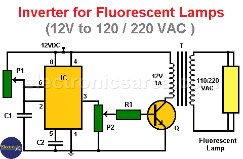
The oscillation frequency of the 555 is given by: f = 0.72 / (R x C) where R is the value given by the potentiometer.
The high and low time of the 555’s output voltage is the same and is equal to: 0.69 x R x C. The idea is to make the multivibrator deliver a signal of approximately 10 kHz.
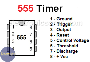
555 Timer Pinout
The square signal coming from the 555 make transistor Q into its cutoff and saturation regions through resistor R1 and potentiometer P2.
The collector of the transistor connected to the transformer gives the secondary winding (12 VAC) a square wave.
As a consequence, in the primary winding (the output connected to the fluorescent tube) there is a square wave voltage of 120VAC or 240VAC.
If we adjust the value of the potentiometer, we can vary the intensity of the current that makes the transistor enter its saturation region and therefore makes the intensity of the collector current that passes through the secondary winding of the transformer vary.
The more current in the base of the transistor, the greater the intensity of light in the fluorescent lamp.
Circuit component list
- 1 555 timer (IC)
- 1 100 ohm resistor (R1)
- 1 1M potentiometer (P1)
- 1 4.7K potentiometer (P2)
- 1 0.01 uF capacitor (C2)
- ? capacitors between (between 0.001 uF and 0.1 uF) (C1)
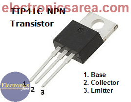
- 1 TIP41 NPN medium power transistor (Q)
- 1 12 VAC to 120 / 240VAC transformer (depending on the voltage of the fluorescent tube) (T)
- 1 40 watts maximum fluorescent lamp
More Power Supply Circuits
- 9V Power Supply circuit (Zener and Transistor)
- 12V Power Supply Circuit (1A)
- Op-Amp–Based 12V Power Supply (Zener and 741)
- 12 volt Power Supply using 7805 regulator
- 15V Power ON delay circuit
- 12 volt to 5 volt Converter Circuit
- 12V to -12V converter circuit using 555
- 12V to 9V Converter Circuit Diagram (PCB)
- 12V to 24V Converter Circuit
- 4 Amp Variable Power Supply Using the LM317
- LM317 4A Variable Power Supply (3 LM317 IC)
- LM350 Voltage Regulator circuit (Variable Power Supply)
- 20A Variable Power Supply (LM317)
- LM338 variable Voltage Regulator (5A)
- Mini variable Power supply circuit (0-30V, 1A)
- 7805 variable voltage regulator circuit (7805 and 741)
- Dual polarity Variable Power Supply (+15V / -15V) max
- Voltage Spike protection Circuit (Voltage Delay Circuit)
- Voltage Regulator circuit (Transistor - Zener)
- Power Supply Dummy load
- Joule Thief Circuit with no Toroid Coil
- 12V to 120 / 220 VAC inverter for fluorescent lamps


