Home / Circuits / Power Supply /
12v to 24v converter circuit
This 12v to 24v converter circuit is very useful for powering devices that work with 24v when we only have a 12v voltage source. The voltage source could be a car battery or similar
How the 12v to 24v converter works?
This 12v to 24v boost converter circuit is based on an oscillator consisting of two NPN bipolar transistors (T1 and T2).
The oscillator handles the transistor T4 that passes from its cutting region to its saturation region continuously.
The transistor T4 is an N-channel MOSFET power transistor capable of conducting a current of up to 18 amps. The coil, which is the element that helps raise the voltage, must be built on a ferrite core and is made of 100 turns of 1 mm cross-section cable.
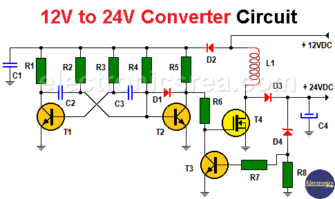
12V to 24V Boost Converter Circuit
Transistor T3 is part of the feedback network and feeds back the output voltage to the gate of the transistor T4, acting when necessary to correct any variation of the output voltage. The output voltage is set using a zener diode D4. The output voltage may be different, if the zener diode is changed to another zener diode of different voltage.
List of components 12v to 24v converter circuit
- 2 2.2K resistors (R1, R4)
- 2 1K resistors (R5, R6)
- 3 4.7K resistors (R2, R3, R7)
- 1 10K resistor (R8)
- 2 100 nF (nanofarad) capacitor (C1, C3)
- 1 10 nF capacitor (C2)
- 1 1000 uF (microfarad) capacitor (C4)
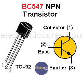
- 3 BC548 NPN bipolar transistors (T1, T2, T3)
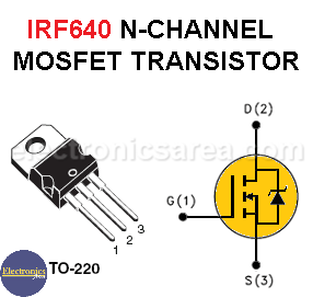
- 1 N-channel MOSFET power transistor IRF640 (T4)
- 3 1N4007 semiconductor diodes (D1, D2, D3)
- 1 24 volt zener diode, 1 watt or more (D4)
- 1 inductor built as mentioned in the text
- 1 heat sink For the MOSFET transistor
More Power Supply Circuits
- 9V Power Supply circuit (Zener and Transistor)
- 12V Power Supply Circuit (1A)
- Op-Amp–Based 12V Power Supply (Zener and 741)
- 12 volt Power Supply using 7805 regulator
- 15V Power ON delay circuit
- 12 volt to 5 volt Converter Circuit
- 12V to -12V converter circuit using 555
- 12V to 9V Converter Circuit Diagram (PCB)
- 12V to 24V Converter Circuit
- 4 Amp Variable Power Supply Using the LM317
- LM317 4A Variable Power Supply (3 LM317 IC)
- LM350 Voltage Regulator circuit (Variable Power Supply)
- 20A Variable Power Supply (LM317)
- LM338 variable Voltage Regulator (5A)
- Mini variable Power supply circuit (0-30V, 1A)
- 7805 variable voltage regulator circuit (7805 and 741)
- Dual polarity Variable Power Supply (+15V / -15V) max
- Voltage Spike protection Circuit (Voltage Delay Circuit)
- Voltage Regulator circuit (Transistor - Zener)
- Power Supply Dummy load
- Joule Thief Circuit with no Toroid Coil
- 12V to 120 / 220 VAC inverter for fluorescent lamps

")

