Home / Circuits / Power Supply /
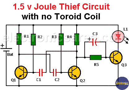
1.5 v Joule Thief Circuit
This 1.5 V Joule Thief circuit allows you to light up a LED. The circuit do not use a toroid coil, so it can not handle a blue or white high intensity LEDs.
Remember that normally the red LEDs light up, barely acceptable way, when there is a minimum of 1.5 volts at its terminals.
Knowing that the voltage drop between the collector and the emitter of transistor Q3 (in series with the LED) is about 0.2 volts, the voltage on the LED will be 1.3 volts and the lighting would be poor.
If you want to use LEDs of other colors such as green and yellow, the lighting will also be inefficient, because the voltage needed to illuminate these LEDs is greater.
To make the LED lights up with good light intensity, we have to increase the voltage applied across its terminals. To achieve this goal, we use an electrolytic capacitor of 1uF, which will “save” or “hold” an additional voltage. This voltage is in series with the 1.5V battery, allowing the LED to emit a light of greater intensity.
How the 1.5 v Joule Thief works?
Looking on the left side of the 1.5 v Joule Thief Circuit diagram, we have transistors Q1, Q2,and associated elements (R1, R2, R3, R4, C1, C2), that work as an astable multivibrator. The multivibrator output is taken from the collector of transistor Q2.
- When transistor Q2 is off, transistor Q3 goes into saturation, so that a current flows through the resistors R4 and R5. The capacitor C3 will be charged to a voltage of about 1 volt.
- When the transistor Q2 goes into saturation, the collector of this transistor is almost 0 volts. So the left terminal of the capacitor (with the “+” sign) is also at 0 volts.
As we said before, the capacitor is already charged and between its terminals there are approximately 1 volt, then at the cathode of the LED we have -1 volt.
From the diagram, we can see that the anode of the LED is connected to +1.5 volts and its cathode is connected to -1 volt. With this, we get a voltage: Vd = 1.5V – (- 1V) = 2.5 volts on LED terminals.
This cycle, with a frequency set by the astable multivibrator, is repeated indefinitely.
With 2.5 volts it is not possible to light up a white or blue high intensity LED, because the supply voltage needed is about 3.7 volts, but if it is possible to turn on a common red, green or yellow LED.
List of circuit components
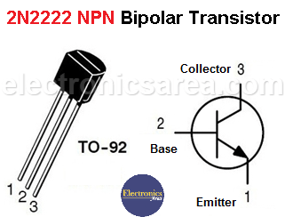
- 3 2N2222A NPN transistors (Q1, Q2, Q3)
- 1 2.2K resistor (R1)
- 2 4.7K resistors (R2, R3)
- 1 100K resistor (R4)
- 1 1K resistor (R5)
- 2 10 nF (nanofarads) capacitor (C1, C2)
- 1 1uF (microfarad) electrolytic capacitor (C3)
- 1 red, green or yellow LED (L1)
- 1 1.5 volt battery (Bat)
More Power Supply Circuits
- 9V Power Supply circuit (Zener and Transistor)
- 12V Power Supply Circuit (1A)
- Op-Amp–Based 12V Power Supply (Zener and 741)
- 12 volt Power Supply using 7805 regulator
- 15V Power ON delay circuit
- 12 volt to 5 volt Converter Circuit
- 12V to -12V converter circuit using 555
- 12V to 9V Converter Circuit Diagram (PCB)
- 12V to 24V Converter Circuit
- 4 Amp Variable Power Supply Using the LM317
- LM317 4A Variable Power Supply (3 LM317 IC)
- LM350 Voltage Regulator circuit (Variable Power Supply)
- 20A Variable Power Supply (LM317)
- LM338 variable Voltage Regulator (5A)
- Mini variable Power supply circuit (0-30V, 1A)
- 7805 variable voltage regulator circuit (7805 and 741)
- Dual polarity Variable Power Supply (+15V / -15V) max
- Voltage Spike protection Circuit (Voltage Delay Circuit)
- Voltage Regulator circuit (Transistor - Zener)
- Power Supply Dummy load
- Joule Thief Circuit with no Toroid Coil
- 12V to 120 / 220 VAC inverter for fluorescent lamps


