Home / Circuits / LED Circuits /
Light Push button circuit with time delay
This Light Push button circuit is useful to illuminate locations where a light source of low power is needed. This circuit is ideal for small or temporary facility locations. Examples of places to use this circuit are: a drawer, a closet, a small room, the car trunk, etc.
The main feature of this circuit is that it turns off the light automatically, avoiding unnecessary energy consumption.
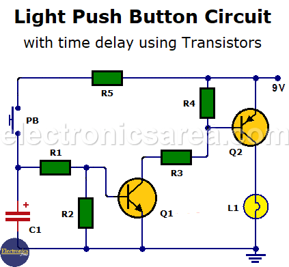
This circuit activates a light, and stays ON for a set time. To activate the light again, you must press the momentary contact button SW1. See the diagram.
If you want a circuit with different set times, the 5 to 30-minute time delay may be a good option.
How the Light Push button circuit works?
The time in which the light remains ON depends on the values of resistor R2 and capacitor C1.
To increase this time, you can change the value of the R2 resistor to a larger one. R2 can also be replaced by a potentiometer to avoid the need to change the resistor with another of different value.
When the SW1 button is pressed, the electrolytic capacitor is charged through resistor R5. The capacitor will have the same voltage of the power supply, and the transistor Q1 gets into its saturation region. This in turn saturates transistor Q2.
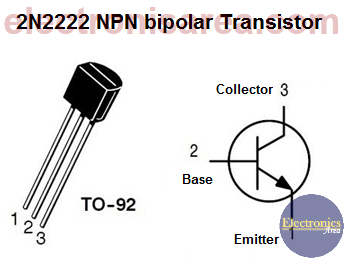
2N2222 NPN bipolar transistor Pinout
Thus, we get the collector of Q2 with a voltage slightly lower than the source voltage and the bulb light ON. This circuit can operate with a 9V battery or 12VDC voltage source.
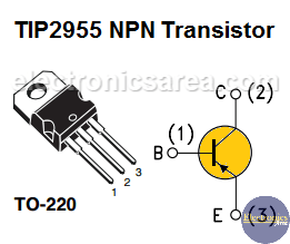
TIP2955 PNP Transistor Pinout
We can replace the light bulb with:
- 2 white LEDs in series with a 100 ohms limiting resistor for a 9V power source, or….
- 3 white LEDs in series with a 100 ohms limiting resistor for a 12V power source.
List of circuit components
- 1 2N2222A NPN transistor (Q1)
- 1 TIP2955 PNP transistor (Q2)
- 1 47 ohms, 1/4 w resistor (R1)
- 1 4.7M, 1/4 w resistor (R2)
- 1 100 ohms 1/4 w resistor (R3)
- 1 2.2K, 1/4 w resistor (R4)
- 1 100 ohms, 1w resistor (R5)
- 1 470uF electrolytic capacitor (C1)
- 1 12V, 2W Bulb (L1). Bulb can be replaced with LEDs. (see the text)
- 1 momentary contact switch, single pole, NO. (SW1)
You can increase the amount of light that the Time Delay Light Switch Circuit radiates, changing the bulb for a larger one. (3 watts, 5 watts)
Note: NO = Normally Open
More LED circuits
- Emergency lighting circuit with LEDs
- Automatic night light circuit with one LED (PCB)
- Bike flashing LED lights circuit
- Flashing LEDs circuit for pedestrians
- Two-way traffic light circuit
- LED sequencer using 4017 decade Counter (LED Chaser)
- Light push button circuit with time delay
- Energy-saving flashing pilot light
- LED connected to 120/240 VAC
- Police style strobe light circuit


")
