Home / Circuits / Power Supply /
Mini variable Power supply from 0 to 30V, 1A
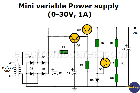
This mini variable power supply is totally transistorized; it can vary its output in a wide range of voltages and can be used for projects where the maximum current consumption is 1 A. The circuit uses only three transistors and, due to its simplicity, is a special project for beginners who want to have a small power supply with great features.
Mini Variable Power Supply Operation
The transformer, the bridge rectifier and the filter
The power supply uses a step-down transformer to obtain a voltage of 24 V in alternating current. This voltage is rectified in full wave by a group of four rectifying diodes (D1, D2, D3, and D4) and then smoothed with capacitor C1, which acts as a filter. You can visit the PS block diagram for more information about a power supply.
The current amplifier
The voltage is then applied to the collectors of transistors Q1 and Q2. Transistors Q1 and Q2 are connected in such a way that they behave like a Darlington transistor. The voltage at the base of transistor Q1 is governed by the collector of transistor Q3, which depends on potentiometer R5.
The voltage regulation
The potentiometer modifies the bias of transistor Q3 and therefore its collector-emitter voltage. The collector voltage of transistor Q3 in turn modifies the voltage at the base of transistor Q2 via transistor Q1.
Transistor Q3 will conduct according to the voltage at its base and in turn will modify the voltage at the base of transistor Q2, which is the transistor that delivers the voltage and current to the load.
Varying the position of the potentiometer arrow varies the voltage of transistor Q3, which in turn controls the voltages and currents of transistors Q1 and Q2.
The set of resistors R4 and R6 and potentiometer R5 form a variable voltage divider that allows the output voltage to be modified.
Electrolytic capacitor C2 helps stabilize the voltage at the base of transistor Q1, and electrolytic capacitor C3 helps stabilize the output voltage of the source.
Circuit Component List
- 1 120/240 to 24 VAC, 1A transformer (T)
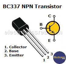
- 2 BC337 NPN 50-volt, 800 mA transistors (Q1, Q3)
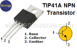
- 1 NPN TIP41 50-volt, 2A transistor (Q2)
- 5 1N4002, 100V, 1A diodes (D1, D2, D3, D4, D5)
- 1 10K potentiometer (R5)
- 2 10K resistors (R1, R2)
- 1 1 kΩ resistor (R3)
- 2 100-ohm resistors (R4, R6)
- 1 1000 uF, 35-volt electrolytic capacitor (C1)
- 2 100 uF, 35-volt electrolytic capacitors (C2, C3)
- 1 heat sink for the NPN TIP41 (Q2) transistor
More Power Supply Circuits
- 9V Power Supply circuit (Zener and Transistor)
- 12V Power Supply Circuit (1A)
- Op-Amp–Based 12V Power Supply (Zener and 741)
- 12 volt Power Supply using 7805 regulator
- 15V Power ON delay circuit
- 12 volt to 5 volt Converter Circuit
- 12V to -12V converter circuit using 555
- 12V to 9V Converter Circuit Diagram (PCB)
- 12V to 24V Converter Circuit
- 4 Amp Variable Power Supply Using the LM317
- LM317 4A Variable Power Supply (3 LM317 IC)
- LM350 Voltage Regulator circuit (Variable Power Supply)
- 20A Variable Power Supply (LM317)
- LM338 variable Voltage Regulator (5A)
- Mini variable Power supply circuit (0-30V, 1A)
- 7805 variable voltage regulator circuit (7805 and 741)
- Dual polarity Variable Power Supply (+15V / -15V) max
- Voltage Spike protection Circuit (Voltage Delay Circuit)
- Voltage Regulator circuit (Transistor - Zener)
- Power Supply Dummy load
- Joule Thief Circuit with no Toroid Coil
- 12V to 120 / 220 VAC inverter for fluorescent lamps


 max")