Home / Circuits / LED Circuits /
Bike Flashing LED Lights Circuit
When we go down the street at night, it is common to find some cyclist that are visible only when they are very close. This is very dangerous situation and could cause many accidents. To avoid this problem, you could use a circuit that lights LEDs in a striking way.
If you’re a cycling fan, and you like biking, night and day, this Bike Flashing LED Lights Circuit is very useful, as it will cause you to be easily visible.
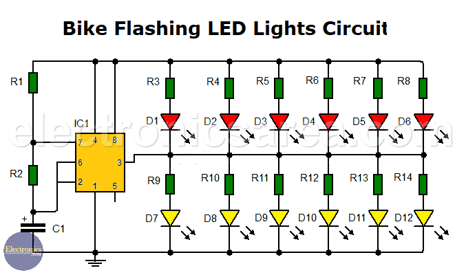
I saw circuit designs that use two 555 integrated circuits and 12 red LEDs, but I managed to change the design in order to use only one 555 timer. With this new, simplified design, lighting times of the 2 groups of LEDs (see diagram) are not equal, but are very close. I think that’s not a problem.
How this Bike Flashing LED lights circuit works?
We will use a 555 timer configured as an astable multivibrator. The output of this multivibrator has a square wave shape.
This circuit has two groups of 6 LEDs.
- The top group will light when the output of 555 is low (approximately 0.75 volts)
- The bottom group will light when the output of 555 is high (approximately 8.4 volts).
This alternating light movement is very striking and easy to see at night.
LEDs can be placed in several ways. They can be placed as shown on the diagram, or you can make your own design to suit the cyclist wishes. This circuit is designed to be used with a 9 volt battery, in order to be portable.
Note: You can also use a combination of white and red LED, in order to increase your visibility.
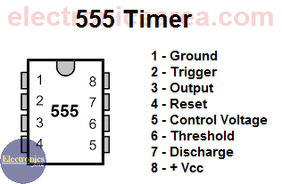
555 timer Pinout
Another interesting circuit that you may be interested in is a flashing LED circuit for night walkers.
List of circuit components for the Flashing LED lights
- 1 x 555 timer IC (IC1)
- 12 x LED: D1 to D12: common red or white LEDs
- 1 x 10K resistor (R1)
- 1 x 100K resistor (R2)
- 12 x 1K resistors (R3 to R14)
- 1 x 10uF electrolytic capacitor (C1)
- 1 x 9 volt battery
The circuit is energized by connecting the positive terminal of the 9-volt battery to the upper terminal of resistor R1 and the negative terminal to the lower terminal of capacitor C1.
More LED circuits
- Emergency lighting circuit with LEDs
- Automatic night light circuit with one LED (PCB)
- Bike flashing LED lights circuit
- Flashing LEDs circuit for pedestrians
- Two-way traffic light circuit
- LED sequencer using 4017 decade Counter (LED Chaser)
- Light push button circuit with time delay
- Energy-saving flashing pilot light
- LED connected to 120/240 VAC
- Police style strobe light circuit


Where do you set the power source though?
Hello Jim
The circuit is energized by connecting the positive terminal of the 9-volt battery to the upper terminal of R1 and the negative terminal to the lower terminal of C1.
Regards