Home / Circuits / Power Supply /
Variable Dummy Load for Power Supply Testing
It is easy to find on the Internet many designs of voltage sources with which we can power our circuit designs. It would be very useful to know how to test a voltage source in order to determine if its characteristics are good or not. To achieve this goal, we can use a variable dummy load, which in this case supports a maximum of 1.5 amps.
The percentage regulation formula
The “percentage regulation” is a characteristic of the voltage source obtained with the formula:
Percentage regulation = ([VNL – VFL] / VFL) x 100
where VNL = no load output voltage and VFL = full load output voltage.
The ideal characteristic of a voltage source (power supply) is to keep the output voltage constant no matter how much current the load requests.
Analyzing the above equation, it can be concluded that this characteristic occurs when the percentage regulation is zero (“0”). (VNL – VFL = 0). Since voltage sources are real, not ideal, it is desirable that this percentage of regulation be as small as possible.
How to use a variable dummy load for power supply testing?
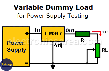
To implement a variable dummy load, a variable voltage regulator LM317 connected as shown in the following diagram is used. Due to its internal design, this voltage regulator has a voltage of 1.25 volts between its output terminals (Out) and adjustment terminals (Adj). So:
The voltage of 1.25 volts is applied to the R and RL series resistors. Thus, the current IL flowing through the load resistor RL (the potentiometer) is IL = 1.25 V / (R + RL).
Since RL is a variable resistor, the current passing through the load (RL) can be varied. In this way, you can test the ability of the power source to give a specific current for a specific voltage value, just by setting the current with the RL potentiometer.
This test can be performed with sources with different output voltages (voltage that is applied to the input (In) of the voltage regulator).
You may be interested in the Power supply block diagram
How to avoid a short circuit when the dummy load = 0?
Since RL is a variable resistor, its value could be “0” ohms, causing a short circuit. To avoid a short circuit, a series resistor R is used to protect the LM317 regulator. The RL and R values are chosen to obtain the minimum and maximum current with which you want to do the test. It is recommended that both R and RL be 2 watts or more.
Notes:
- Take into account that the maximum current that the LM317 can give is 1.5 amps. Also take into account the maximum current that can be supplied by the source to be tested, so as not to exceed it and damage it. If you want the power supply to give more current, you have to use a circuit with higher capacity.
- (Very important) The voltage regulator must have a large heat sink due to the large amount of current and voltage it could withstand. A computer fan can be placed to reduce the temperature, if necessary. A large microprocessor heater plus a corresponding fan can be used.
- It would be convenient to place an ammeter in series with the resistor R.
- The tests must be done for a limited period of time.
More Power Supply Circuits
- 9V Power Supply circuit (Zener and Transistor)
- 12V Power Supply Circuit (1A)
- Op-Amp–Based 12V Power Supply (Zener and 741)
- 12 volt Power Supply using 7805 regulator
- 15V Power ON delay circuit
- 12 volt to 5 volt Converter Circuit
- 12V to -12V converter circuit using 555
- 12V to 9V Converter Circuit Diagram (PCB)
- 12V to 24V Converter Circuit
- 4 Amp Variable Power Supply Using the LM317
- LM317 4A Variable Power Supply (3 LM317 IC)
- LM350 Voltage Regulator circuit (Variable Power Supply)
- 20A Variable Power Supply (LM317)
- LM338 variable Voltage Regulator (5A)
- Mini variable Power supply circuit (0-30V, 1A)
- 7805 variable voltage regulator circuit (7805 and 741)
- Dual polarity Variable Power Supply (+15V / -15V) max
- Voltage Spike protection Circuit (Voltage Delay Circuit)
- Voltage Regulator circuit (Transistor - Zener)
- Power Supply Dummy load
- Joule Thief Circuit with no Toroid Coil
- 12V to 120 / 220 VAC inverter for fluorescent lamps


 max")
