Home / Circuits / Power Supply /
LM350 Adjustable Voltage Regulator
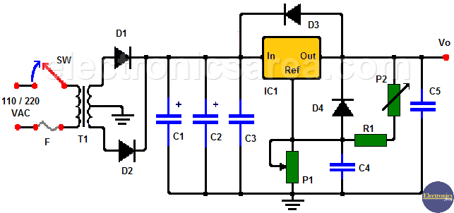
This variable power supply uses the LM350 adjustable voltage regulator and can deliver 1.25 to 16 volts and a maximum current of 3 amps.
The LM350 voltage regulator can deliver a higher current than the LM317. This is very useful as it can be used with circuits or equipment that demand more current. The formula for the output voltage is the same for both regulators.
Variable voltage source operation
The formula for the output voltage is: Vo = 1.25 (1 + R2 / R1) + Iadj x R2.
The current Iadj, which is the current that passes through the Adj (adjustment) pin of the regulator, is negligible, this means that the product Iadj x R2 can be neglected.
So the formula is simplified, and we get: Vo = 1.25 (1 + R2 / R1). In our case, P1 is equal to R2 and (R1 + P2) is equal to R1. (see diagram).
This source is very easy to implement, as the LM350 voltage regulator internally incorporates protection against excess current consumption.
LM350 adjustable power supply (Variable Power Supply)
Final voltage source adjustment
Adjustment after the circuit is fully assembled is very important.
To achieve this adjustment, the potentiometer P1 is regulated until the output voltage is maximum and then the potentiometer P2 is regulated until obtaining 16 volts in Vo.
Diodes are for protection and prevent capacitors from discharging (when the voltage source is turned off) through low current points within the regulator.
- D3 protects against C5 discharge
- D4 protects against C4 discharge.
- Capacitor C3 is recommended for any application that has the regulator located away from the voltage source.
- Capacitor C4 serves to improve ripple at the regulator output and …
- Capacitor C5 serves to improve the output impedance.
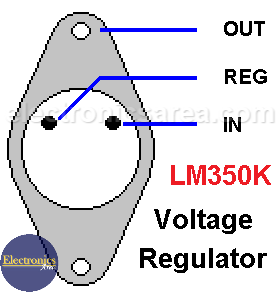
LM350 voltage regulator pin out
Circuit component list
- 1 LM350 voltage regulator (IC1)
- 2 4700 uF (microfarads) electrolytic capacitors (C1, C2)
- 1 0.1uF (microfarads) tantalum capacitor (C3)
- 1 10 uF tantalum capacitor (C4)
- 1 1 uF capacitor (C5)
- 2 6A, 200 volts or more rectifier diodes (D1, D2)
- 2 1N4002 or equivalent diodes (D3, D4)
- 1 5K potentiometer (P1)
- 1 100 ohm potentiometer (P2)
- 1 110/220 at 32 volts, 3 amps transformer with central thread (T)
- 1 250 mA fuse (F)
- 1 switch (SW)
You may also be interested in: LM317 Variable Voltage Regulator Circuit or a Dual polarity variable voltage source.
More Power Supply Circuits
- 9V Power Supply circuit (Zener and Transistor)
- 12V Power Supply Circuit (1A)
- Op-Amp–Based 12V Power Supply (Zener and 741)
- 12 volt Power Supply using 7805 regulator
- 15V Power ON delay circuit
- 12 volt to 5 volt Converter Circuit
- 12V to -12V converter circuit using 555
- 12V to 9V Converter Circuit Diagram (PCB)
- 12V to 24V Converter Circuit
- 4 Amp Variable Power Supply Using the LM317
- LM317 4A Variable Power Supply (3 LM317 IC)
- LM350 Voltage Regulator circuit (Variable Power Supply)
- 20A Variable Power Supply (LM317)
- LM338 variable Voltage Regulator (5A)
- Mini variable Power supply circuit (0-30V, 1A)
- 7805 variable voltage regulator circuit (7805 and 741)
- Dual polarity Variable Power Supply (+15V / -15V) max
- Voltage Spike protection Circuit (Voltage Delay Circuit)
- Voltage Regulator circuit (Transistor - Zener)
- Power Supply Dummy load
- Joule Thief Circuit with no Toroid Coil
- 12V to 120 / 220 VAC inverter for fluorescent lamps


