Home / Circuits / Power Supply /
Dual Polarity Variable Power Supply
This dual-polarity variable power supply provides two independent voltage outputs. One positive and one negative, with a maximum amplitude of +/- 15 volts and a current of up to 1.5 amps.
This power supply is ideal for powering dual-polarity circuits, such as some audio amplifiers and op-amp applications. If you need a more powerful power source, the 3-amp variable voltage source may be right for you.
How Does the Dual Polarity Variable Power Supply Work?
The LM137 and LM337 voltage regulators
This voltage source uses the LM317 variable voltage regulator for the positive voltage output (from 1.2 to 15 volts) and the LM337 variable voltage regulator for the negative voltage output (from -1.2 to -15 volts). Two potentiometers are used to vary the output voltage. See the diagram.
Every regulator needs a heat sink; the bigger, the better. If the use of the power supply is constant, a fan can be placed to cool the heat sinks.
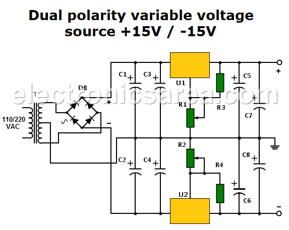
Dual polarity variable power supply (+15V / -15V) max.
How the 0-volt output is achieved
Remember that these regulators have the limitation of not being able to deliver a voltage equal to or less than 1.2 volts in the case of positive voltage output and -1.2 volts in the case of negative voltage output.
To solve this problem, two rectifier diodes (e.g., 1N4003) can be connected in series to the output of each regulator, resulting in a voltage drop of 0.6V + 0.6V = 1.2V.
This modification will cause the final output to always be reduced by this voltage and thus deliver “0 volts,” but for most applications this is not a problem. (Diodes are not shown in the schematic.)
How do capacitors function?
The electrolytic capacitors C1, C2, C3, and C4 are the filters that flatten the output wave from the diode bridge before it enters each regulator. Capacitors C5, C6, C7, and C8 are used to improve transient response.
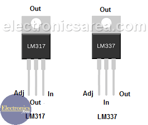
Pin Assignments for LM317 and LM337 Voltage Regulators
Dual Polarity Variable Power Supply Components List
- 2 240-ohm, ¼ watt resistors: (R3, R4)
- 2 5K potentiometers (R1, R2)
- 2 2200uF / 35V electrolytic capacitors (C1, C2)
- 4 1μF / 35 Volt capacitors (C3, C4, C5, C6)
- 2 100μF / 35 Volt electrolytic capacitors (C7, C8)
- 1 2-amp diode bridge (DB)
- 1 LM317 positive voltage regulator (U1)
- 1 LM337 Negative Regulator (U2)
- 2 heat sinks, for U1, U2
- 1 switch to place on primary of transformer
- 1 110/220 to 30VAC, 2 Amp, Center Tapped Transformer (T)
More Power Supply Circuits
- 9V Power Supply circuit (Zener and Transistor)
- 12V Power Supply Circuit (1A)
- Op-Amp–Based 12V Power Supply (Zener and 741)
- 12 volt Power Supply using 7805 regulator
- 15V Power ON delay circuit
- 12 volt to 5 volt Converter Circuit
- 12V to -12V converter circuit using 555
- 12V to 9V Converter Circuit Diagram (PCB)
- 12V to 24V Converter Circuit
- 4 Amp Variable Power Supply Using the LM317
- LM317 4A Variable Power Supply (3 LM317 IC)
- LM350 Voltage Regulator circuit (Variable Power Supply)
- 20A Variable Power Supply (LM317)
- LM338 variable Voltage Regulator (5A)
- Mini variable Power supply circuit (0-30V, 1A)
- 7805 variable voltage regulator circuit (7805 and 741)
- Dual polarity Variable Power Supply (+15V / -15V) max
- Voltage Spike protection Circuit (Voltage Delay Circuit)
- Voltage Regulator circuit (Transistor - Zener)
- Power Supply Dummy load
- Joule Thief Circuit with no Toroid Coil
- 12V to 120 / 220 VAC inverter for fluorescent lamps
dual-polarity-variable-voltage-source


