Home / Circuits / Power Supply /
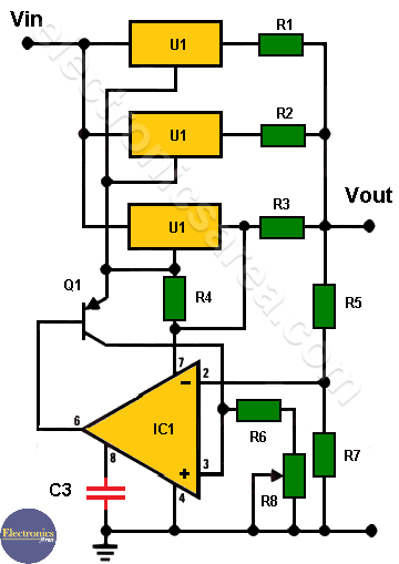
4 Amp Variable Power Supply with 3 LM317s
A 4 amp variable power supply can be created without pass-through transistors. When transistors are used, they are used to being placed in parallel to increase the current delivered to the load.
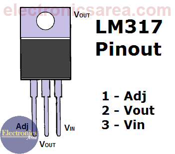
In this case we will do something similar but using variable voltage regulators. We are going to use three LM317-N voltage regulators in parallel to increase the current capacity of the entire regulator to the load. See LM317 voltage regulator pin out.

LM317 Voltage Regulator Pin Out
4 Amp Variable Power Supply Operation
The output voltage is set using a variable resistor (potentiometer) connected to the non-inverting terminal of the precision op amp (IC1), and the reference current of the transistor is obtained through the 100 ohm resistor (R4).
When the output voltage is increased above the correct value, the op-amp makes the correction by removing current from the base of transistor Q1, bringing the transistor closer to its cutoff state.
4 Amp Variable Power Supply with 3 LM317s
In this way, the voltage at the adjusting pins (ADJ) of the regulators decreases, in turn decreasing the output voltage.
Resistors R1, R2, R3 are used in series with regulators to match the final output voltage. This is done due to possible differences in the outputs of each of the LM317 regulators.
The unregulated voltage from this source is achieved by using a step-down transformer, a diode bridge to rectify the alternating signal, and two capacitors in parallel to flatten the signal. See the following diagram.
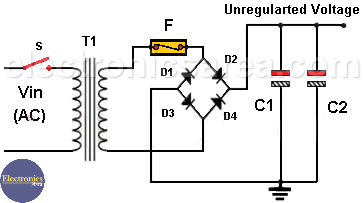
Unregulated power source
Power Supply Circuit component list
- 3 LM317-N variable voltage regulators (U1, U2, U3)
- 1 LM308 or NTE938 precision op amp (IC1)
- 1 2N2905 PNP transistor (Q1)
- 3 0.2 ohm resistors (R1, R2, R3)
- 1 100 ohm resistor (R4)
- 2 5K resistors (R5, R7)
- 1 150 ohm resistor (R6)
- 1 1.5K potentiometer (R8)
- 2 2200 microfarads 50 V electrolytic capacitors of (C1, C2)
- 1 200 pF (picofarads) capacitor (C3)
- 1 Transformer, 24 V in the secondary. (T1)
- 4 4 Amp rectifier diodes (D1, D2, D3, D4)
- 1 fuse (F). 1 amp for 110V, 0.5 amp for 220V.
- 1 switch (S)
More Power Supply Circuits
- 9V Power Supply circuit (Zener and Transistor)
- 12V Power Supply Circuit (1A)
- Op-Amp–Based 12V Power Supply (Zener and 741)
- 12 volt Power Supply using 7805 regulator
- 15V Power ON delay circuit
- 12 volt to 5 volt Converter Circuit
- 12V to -12V converter circuit using 555
- 12V to 9V Converter Circuit Diagram (PCB)
- 12V to 24V Converter Circuit
- 4 Amp Variable Power Supply Using the LM317
- LM317 4A Variable Power Supply (3 LM317 IC)
- LM350 Voltage Regulator circuit (Variable Power Supply)
- 20A Variable Power Supply (LM317)
- LM338 variable Voltage Regulator (5A)
- Mini variable Power supply circuit (0-30V, 1A)
- 7805 variable voltage regulator circuit (7805 and 741)
- Dual polarity Variable Power Supply (+15V / -15V) max
- Voltage Spike protection Circuit (Voltage Delay Circuit)
- Voltage Regulator circuit (Transistor - Zener)
- Power Supply Dummy load
- Joule Thief Circuit with no Toroid Coil
- 12V to 120 / 220 VAC inverter for fluorescent lamps

 max")

 - Power Factor Formulas")