Home / Circuits / Power Supply /
How to make a 12V 1A power supply?
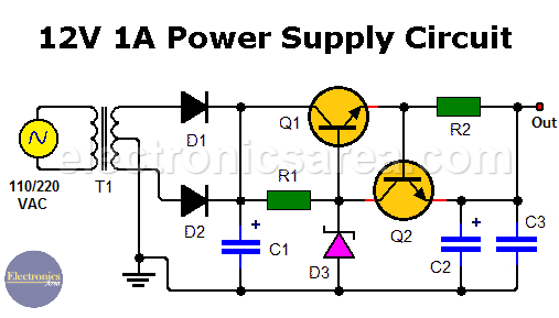
This 12V 1A power supply using zener diode and transistors allows us to obtain an output of approximately 11.4 volts with a very small percentage variation for a wide variety of loads. Output voltage could be 12.4 volts using a different zener diode.
The transistor (Q1) is used to expand the current capacity that this voltage source can deliver. If only the zener diode is used, the amount of current delivered by this source would be limited to a few tens of milliamps.
This voltage source uses transistor Q2 to protect itself from excessive current consumption or a short circuit. The advantage of this 12VDC source, compared to a voltage source that uses an integrated voltage regulator like the LM7812, is that it has a lower percentage variation of the output voltage.
This feature is very desired in some cases. In a typical 7812 voltage regulator, this variation can be close to 5% up and down from the expected 12V at the output (11.5 to 12.5 Volts).
How the 12V 1A power supply works?
This voltage source consists of a step-down transformer, two rectifier diodes and an electrolytic capacitor, which allows us to obtain the part of the power supply that is not regulated. To stabilize the voltage, we use a 12V zener diode as the main component.
The zener has the NPN transistor (Q1) base connected to its cathode. In this way it is achieved that in the emitter of the transistor there is the voltage of the zener diode minus 0.6 volts (base-emitter voltage drop).
The voltage at the emitter of Q1 minus the voltage drop at resistor R2 is the voltage that is obtained at the output. Due to the small value resistor R2 has (it is designed for this purpose), the voltage drop in this element is neglected.
The Q2 transistor function (overcurrent protection) is closely linked to resistor R2. When the current increases too much or there is a short circuit, the voltage drop across the resistor increases until there are 0.6 volts between its terminals. This happens approximately when the current in the load is 1.2 amps. If we want the source to be protected when less current is consumed, we must increase the value of R2 to a different one.
These 0.6 volts are directly applied to the emitter base junction of transistor Q2, which starts conducting and removes the current entering the base of transistor Q1.
As a consequence, the emitter current of transistor Q1 decreases, which is equivalent to decreasing the current to the load, thus protecting the voltage source.
If you prefer to use an Operational Amplifier instead of transistors, you could be interested in a 12V Power Supply that use a zener diode and a 741 op. amp.
List of components of the 12V power 1A supply circuit
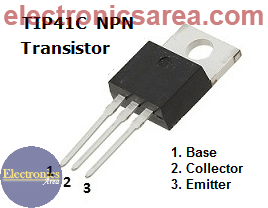
- 1 NPN TIP41C or TIP41A bipolar transistor (Q1)
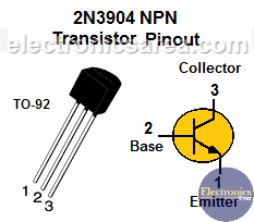
- 1 NPN 2N3904 bipolar transistor (Q2)
- 2 1N5400 rectifier diodes (D1, D2)
- 1 1N4742 zener diode (12V) (D3)
- 1 10K, 1/4 w resistor (R1)
- 1 0.5 ohms, 2w resistor (R2)
- 1 2200 uF / 35V electrolytic capacitor (C1)
- 1 10 uF / 35V electrolytic capacitor (C2)
- 1 0.01 uF capacitor (C3)
- 1 240/120VAC to 24VAC transformer, 1.5 A (T)
- 1 Heatsink (for the Q1 transistor)
Note: If a 13V zener diode (1N4743) is used, the output voltage will be 12.4 volts.
More Power Supply Circuits
- 9V Power Supply circuit (Zener and Transistor)
- 12V Power Supply Circuit (1A)
- Op-Amp–Based 12V Power Supply (Zener and 741)
- 12 volt Power Supply using 7805 regulator
- 15V Power ON delay circuit
- 12 volt to 5 volt Converter Circuit
- 12V to -12V converter circuit using 555
- 12V to 9V Converter Circuit Diagram (PCB)
- 12V to 24V Converter Circuit
- 4 Amp Variable Power Supply Using the LM317
- LM317 4A Variable Power Supply (3 LM317 IC)
- LM350 Voltage Regulator circuit (Variable Power Supply)
- 20A Variable Power Supply (LM317)
- LM338 variable Voltage Regulator (5A)
- Mini variable Power supply circuit (0-30V, 1A)
- 7805 variable voltage regulator circuit (7805 and 741)
- Dual polarity Variable Power Supply (+15V / -15V) max
- Voltage Spike protection Circuit (Voltage Delay Circuit)
- Voltage Regulator circuit (Transistor - Zener)
- Power Supply Dummy load
- Joule Thief Circuit with no Toroid Coil
- 12V to 120 / 220 VAC inverter for fluorescent lamps
 - Power Factor Formulas")


