Home / Circuits / Power Supply /
How to make a 4 Amp variable power supply using LM317 and a boost transistor?
This 4 Amp variable power supply using an LM317 voltage regulator and a current boosting transistor is useful when we want a variable power supply with more current than a single LM317 regulator can provide.
The LM317 can only provide a maximum of 1.5 amps, and in many cases this will not be sufficient.
How does the Variable power supply work?
The operation of this voltage source can be understood by analyzing the values of resistors R2 and R3.
The current flowing through the LM317 voltage regulator passes through diode D5 and resistor R3. The diode has a voltage drop of 0.7V, which is equal to the base-emitter voltage (VEB) of transistor Q1. Therefore, the voltage across R2 is equal to the voltage across R3.
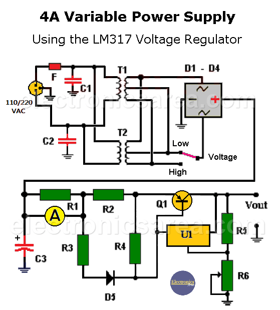
4 Amp Variable Voltage Source Using an LM317 and a Current Boost Transistor
Since R2 = 0.3 x R3, three times the current flows through the transistor than through the regulator.
Therefore, the total current that the circuit can deliver is four times greater than if the LM317 regulator were used alone. In addition, the current limiting capability of the LM317 applies to the entire circuit.
Resistor R1 is placed in front of the regulator-transistor assembly so as not to affect the output voltage, and is used to measure the current delivered to the load. I = V / R, since R = 1 Ω, then I = V.
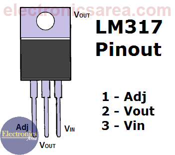
LM317T Voltage Regulator Pinouts
Then only the voltage at the ends of this resistor is measured, but the multimeter reading is interpreted as a current.
The voltage regulator has a high/low voltage selector switch. This switch is used to select between two different voltages at the input of the diode bridge. If the source output voltage is very low, it is better to select the low voltage option to avoid the regulator and transistor having to dissipate a large amount of power.
A power source using 3 LM317 voltage regulators and a precision op amp is another version of a 4 amp power supply.
Circuit components list
- 1 LM317T monolithic variable voltage regulator (U1)
- 1 PNP 276-2043, NTE 219 or similar transistor (Q1)
- 5 common 50V/25A rectifier diodes or a bridge rectifier with the same characteristics
- 1 1 Ω, 1 watt resistor (R1)
- 1 0.1 Ω, 5 watt resistor (R2)
- 1 0.33 Ω, 5 watt resistor (R3)
- 1 10 Ω, 2 watt resistor (R4)
- 1 220 Ω, 1/2 watt resistor (R5)
- 1 2.5 KΩ potentiometer (R6)
- 2 0.01 uF / 1 KV (1000 volts) capacitors (C1, C2)
- 1 3300 uF / 35 volts or greater electrolytic capacitor (C3)
- 2 110 / 220 to 18 Vac center-tapped transformers, 4 to 5 amps
- 1 1 Amp Fuse
- 1 Main Circuit Breaker
- Two-position switch (low voltage / high voltage). See diagram.
- 2 heat sinks, for the LM317 regulator and the Q1 pass transistor.
More Power Supply Circuits
- 9V Power Supply circuit (Zener and Transistor)
- 12V Power Supply Circuit (1A)
- Op-Amp–Based 12V Power Supply (Zener and 741)
- 12 volt Power Supply using 7805 regulator
- 15V Power ON delay circuit
- 12 volt to 5 volt Converter Circuit
- 12V to -12V converter circuit using 555
- 12V to 9V Converter Circuit Diagram (PCB)
- 12V to 24V Converter Circuit
- 4 Amp Variable Power Supply Using the LM317
- LM317 4A Variable Power Supply (3 LM317 IC)
- LM350 Voltage Regulator circuit (Variable Power Supply)
- 20A Variable Power Supply (LM317)
- LM338 variable Voltage Regulator (5A)
- Mini variable Power supply circuit (0-30V, 1A)
- 7805 variable voltage regulator circuit (7805 and 741)
- Dual polarity Variable Power Supply (+15V / -15V) max
- Voltage Spike protection Circuit (Voltage Delay Circuit)
- Voltage Regulator circuit (Transistor - Zener)
- Power Supply Dummy load
- Joule Thief Circuit with no Toroid Coil
- 12V to 120 / 220 VAC inverter for fluorescent lamps


 max")
