
2-LED Temperature change indicator circuit
This 2-LED temperature change indicator shows us, by means of two LEDs, when the sensed temperature is above or below a set limit. When the temperature is above the preset temperature level, LED D1 will light up, and if it is below, LED D2 will light up.
How does the 2-LED temperature change indicator work?
The temperature sensor used is the LM35. The LM35 increases its output voltage by 10 mV for each degree Celsius (°C) increase in the temperature sensed.
The potentiometer R2 is used to set the voltage that will change the operational amplifier to the positive saturation state and that will turn ON the red LED.
When the output voltage of the LM35 is equal to or greater than the set voltage.
When the output voltage of the LM35 is equal to or greater than the voltage set by the potentiometer connected to the operational inverter pin. The operational amplifier changes to the positive saturation state, saturating the transistor Q1 as well. With transistor Q1 in saturation mode, LED D1 turns ON, transistor Q2 enters the cut-off mode, and LED D2 turns OFF.
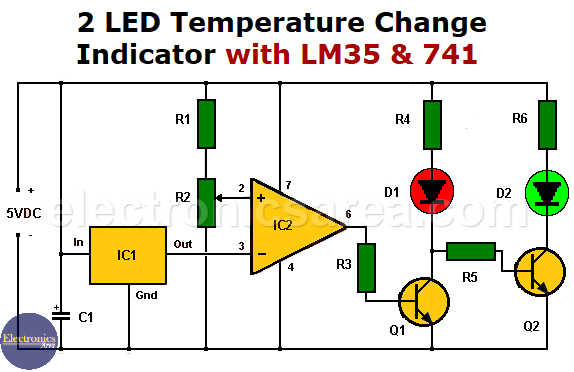
2 LED Temperature Change Indicator with LM35 & 741
When the output voltage of the LM35 is less than the set voltage.
When the output voltage of the LM35 is less than the voltage set by the potentiometer connected to the operational amplifier inverter pin, it changes to the negative saturation state and causes transistor Q1 to go into cutoff mode (not conducting) and LED D1 to turn off.
The cutoff mode of Q1 causes the transistor Q2 to go into saturation mode, and LED D2 lights up.
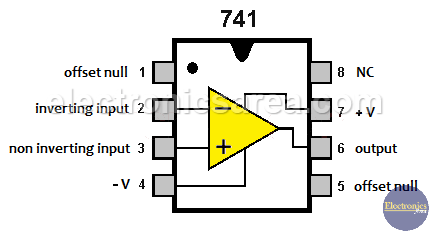
The 741 operational amplifier pinout
For example, we want to detect when the temperature is equal to or greater than 50°C.
If the reference voltage is 0.5V (inverter pin set to activate the operational amplifier when the temperature reaches 50°C) and the voltage at the non-inverting input of the operational amplifier (LM35 output) is 0.5V (the temperature is 50°C), then the following occurs:
The output of IC2 goes to positive saturation. This causes transistor Q1 to saturate and D1 to turn on. As the collector of Q1 is connected to the base of Q2, it will cause it to enter into cut.
When the temperature is below 50°C, the operation of the operational amplifier and transistors is reversed. So the D1 LED turns off and the D2 LED lights up.
List of circuit components
- 1 LM35 temperature sensor (IC1)
- 1 741 Operational Amplifier (IC2)
- 2 2N2222 NPN transistors or similar (Q1, Q2)
- 3 10K resistors (R1, R3, R5)
- 2 220-ohm resistors (R4, R6)
- 1 5K potentiometer (R2)
- 1 10 μF (microfarad) electrolytic capacitor (C1)
- 2 LEDs, 1 red (D1), 1 green (D2)
Note: The circuit must use a 5 VDC power supply.
More Detector Circuits
- Light detector circuit using LDR (automatic night light)
- How to make a Light Sensitive Sound Generator Circuit?
- Light activated switch circuit with LDR and Op Amp
- Light Operated Relay Circuit using LDR / Photoresistor
- Twilight Switch Circuit
- Dark detector circuit using LDR and relay
- Darkness detector circuit with audio output using 555
- Temperature Gauge Circuit Using LM324 (PCB)
- Temperature to Voltage Converter using Thermistor (PCB)
- Rain Detector using two Transistors
- 2 LED Temperature Change Indicator with LM35 & 741
- Lie Detector Circuit Using Two Transistors
- Humidity sensor circuit using the 555 timer
- Blown Fuse Indicator Circuit using one transistor
- Electronic sound control Circuit (applause)
- Photodiode Amplifier Circuit – Current-to-Voltage Converter


