Home / Circuits / Power Supply /
5A Variable Power Supply with LM338 voltage regulator
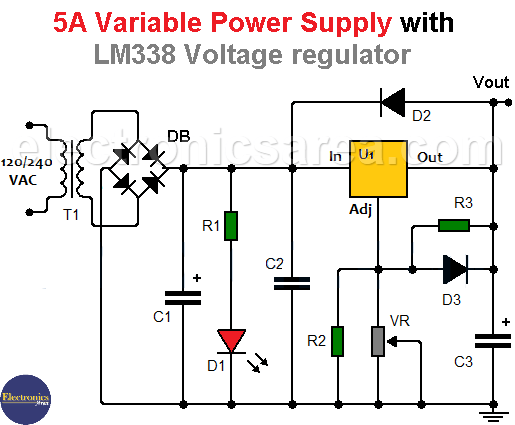
The 5A Variable Power Supply uses the LM338 voltage regulator. This is a three terminal adjustable regulator that is capable of delivering up to 5A at a voltage range of 1.2 to 30 volts.
This regulator has the special characteristic that it allows current peaks of up to 12A, for a short period of time. A thermal overload protection is also included in the regulator.
The LM338 regulator works the same as the lm317 adjustable voltage regulator circuit, known to all.
5 A adjustable Voltage Supply Operation
The signal from the secondary winding, now reduced in voltage, is applied to a diode bridge (DB) that rectifies it, and is then flattened by the electrolytic capacitor C1 (filter).
At this time the signal at the positive terminal of capacitor C1 is about 33VDC unregulated. At this point a LED (D1), with its limiting resistor, is placed in order to indicate the operation of the power source.
The signal on the capacitor is applied to the input of the voltage regulator (In). The voltage at the regulator output (Out) will depend on the value of the voltage that exists in the adjustment pin (Adj) of the regulator. This voltage can be changed by means of the VR potentiometer connected to the adjustment pin (Adj).
The output voltage is obtained by the following formula: Vout = 1.25 (1+ VR / R3)
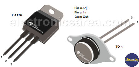
LM338 Variable Voltage Regulator Packages
5A Variable Power Supply Component List
- 1 120/240 to 24VAC transformer (T)
- 1 LM338 variable voltage regulator (U1)
- 1 10 A, 400 V diode bridge (DB)
- 1 10,000 uF (microfarads) electrolytic capacitor (C1)
- 1 2,200 uF (microfarads) electrolytic capacitor (C3)
- 1 0.1 uF (microfarads) capacitor (C2)
- 1 2.7 k resistor (R1)
- 1 12 k resistor (R2)
- 1 220 ohm resistor (R3)
- 1 10k potentiometer (VR)
- 2 1N4007 rectifier diodes (D2, D3)
- 1 red LED (D1)
More Power Supply Circuits
- 9V Power Supply circuit (Zener and Transistor)
- 12V Power Supply Circuit (1A)
- Op-Amp–Based 12V Power Supply (Zener and 741)
- 12 volt Power Supply using 7805 regulator
- 15V Power ON delay circuit
- 12 volt to 5 volt Converter Circuit
- 12V to -12V converter circuit using 555
- 12V to 9V Converter Circuit Diagram (PCB)
- 12V to 24V Converter Circuit
- 4 Amp Variable Power Supply Using the LM317
- LM317 4A Variable Power Supply (3 LM317 IC)
- LM350 Voltage Regulator circuit (Variable Power Supply)
- 20A Variable Power Supply (LM317)
- LM338 variable Voltage Regulator (5A)
- Mini variable Power supply circuit (0-30V, 1A)
- 7805 variable voltage regulator circuit (7805 and 741)
- Dual polarity Variable Power Supply (+15V / -15V) max
- Voltage Spike protection Circuit (Voltage Delay Circuit)
- Voltage Regulator circuit (Transistor - Zener)
- Power Supply Dummy load
- Joule Thief Circuit with no Toroid Coil
- 12V to 120 / 220 VAC inverter for fluorescent lamps


