Voltage Drop Alarm Circuit
This voltage drop alarm circuit is useful for monitoring or testing power supplies. Sometimes, it is necessary to monitor the voltage and take action when it drops below an acceptable level.
If we only have a multimeter, we can supplement it with a circuit that monitors the voltage and sounds an alarm when the voltage drops or the power source fails.
The circuit will keep the buzzer active even after the voltage returns to normal. The buzzer will stay on until the reset button is pressed.
Operation of the Voltage Drop Alarm Circuit
The circuit uses an LM393 integrated circuit (IC) with two comparators (U1) and a programmable voltage reference of 2.5 V on its non-inverting input. A three-terminal shunt regulator (VR) provides the voltage reference. See the figure.
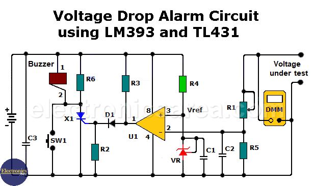
The comparator compares the voltage reference (V_(ref)) with the voltage source’s output by dividing it with potentiometer R₁ and resistor R₅. The potentiometer (R1) adjusts the voltage under test.
When the test voltage drops below the reference voltage, the comparator output changes from low to high, which triggers the thyristor. The thyristor then turns on. This activates the buzzer, which begins sounding. The buzzer remains active until switch SW1 is pressed momentarily.
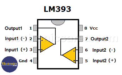
LM393: Very Low Voltage Offset Comparators
Resistor R6, in parallel with the buzzer, ensures that the current through the SCR (X1) keeps the buzzer on, even when the comparator output goes low. The circuit can be powered by a 9-volt battery or an external power source.
With the test voltage active, use a digital voltmeter to measure the voltage across R5 until it exceeds the reference voltage by the desired amount.
Then, connect the digital multimeter in parallel with the test voltage to see the results visually. The alarm should sound when the test voltage drops below the reference voltage.
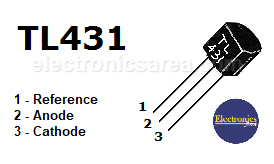
TL431: Programmable Precision Voltage Reference
List of components for the voltage drop alarm circuit:
- 1 x LM393 integrated circuit. (2 comparators on one chip) (U1)
- 1 x TL431, a programmable precision reference (VR)
- 1 x thyristor 2N5060 or equivalent (X1)
- 1 x diode 1N5060 or the equivalent (X1)
- 1 x diode 1N4148 or equivalent (D1)
- 1 x 47K potentiometer (R1)
- 1 x 2.2K resistor (R2)
- 1 x 10K resistor (R3)
- 1 x 6.8K resistor (R4)
- 1 x 4.7K resistor (R5)
- 1 x 1K resistor (R6)
- 2 x 0.01 µF capacitors (C1 and C2)
- 1 x capacitor of 0.1 uF (C3)
- 1 x buzzer
- 1 x normally open (NO) switch (SW1)
Based on the article by John Lo Giudice
")


