Home / Circuits / Power Supply /
15V Power Source ON delay
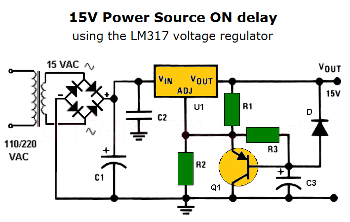
This 15V power source ON delay uses the well-known voltage regulator LM317 configured to have 15 volts in its output. This voltage source also uses a bipolar PNP transistor and an electrolytic capacitor, to achieve a delayed activation of the voltage regulator. See the image below.
This type of application is very useful when it is necessary to prevent a large amount of current from passing to the load when the voltage source is turned on.
How the 15V power source ON delay?
As the input voltage starts increasing at the Vin terminal of the voltage regulator, transistor Q1 sets the regulator pin Adj to zero volts. This is because the base of the transistor is practically connected to ground through the electrolytic capacitor C3, which initially is completely discharged.
At the beginning, the output voltage of the voltage source is the sum of the reference voltage of 1.25 V plus the voltage drop between the base and the emitter of the transistor. (Initially, VCE = 0 volts)
As time passes, capacitor C3 begins to charge and eventually the voltage at the base of the transistor increases. Thus, the transistor Q1 enters the cut-off region, (there is no emitter-collector current) and the emitting collector voltage (VCE = 13.75V)
At this time, the regulator operates normally and has 15 V regulated at its output. The output voltage is established by resistors R1 and R2. The semiconductor diode D is placed between the positive terminal of the capacitor C1 and the output Vout to provide a discharge path for the capacitor.
List of components of the 15V power source ON delay
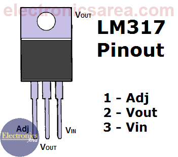
- 1 LM317-N voltage regulator (U1)
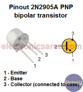
- 1 PNP 2N2905 bipolar transistor or similar (Q1)
- 1 110/220 VAC at 15 VAC, 1.5 A transformer
- 1 1N4002 rectifying diode or similar (D)
- 1 2 Amp bridge rectifier
- 1 2.7k resistor (R1)
- 1 240 ohm resistor (R2)
- 1 50k resistor (R3)
- 1 2200 uF (microfarad), 25 V or more electrolytic capacitor (C1)
- 1 0.1 uF capacitor (microfarads) (C2)
- 1 25 uF (microfarads), 25 V or more electrolytic capacitor (C3)
More Power Supply Circuits
- 9V Power Supply circuit (Zener and Transistor)
- 12V Power Supply Circuit (1A)
- Op-Amp–Based 12V Power Supply (Zener and 741)
- 12 volt Power Supply using 7805 regulator
- 15V Power ON delay circuit
- 12 volt to 5 volt Converter Circuit
- 12V to -12V converter circuit using 555
- 12V to 9V Converter Circuit Diagram (PCB)
- 12V to 24V Converter Circuit
- 4 Amp Variable Power Supply Using the LM317
- LM317 4A Variable Power Supply (3 LM317 IC)
- LM350 Voltage Regulator circuit (Variable Power Supply)
- 20A Variable Power Supply (LM317)
- LM338 variable Voltage Regulator (5A)
- Mini variable Power supply circuit (0-30V, 1A)
- 7805 variable voltage regulator circuit (7805 and 741)
- Dual polarity Variable Power Supply (+15V / -15V) max
- Voltage Spike protection Circuit (Voltage Delay Circuit)
- Voltage Regulator circuit (Transistor - Zener)
- Power Supply Dummy load
- Joule Thief Circuit with no Toroid Coil
- 12V to 120 / 220 VAC inverter for fluorescent lamps


