Main Power failure alarm and battery backup circuit
This Main Power failure alarm circuit tells us when the electricity that powers a system or circuit, is gone.
How the Power failure alarm circuit works?
This Main Power failure alarm circuit is connected to the power grid via the transformer T1. The AC voltage is rectified by the diode D1 and is flattened by the electrolytic capacitor C1.
When there is a voltage on the anode of D2 (12 volts or more), there is energy and everything is ok. The transistor Q1 is in saturation while maintaining the gate of the SCR (TR1) at a low voltage level. The SCR is not triggered, there is no current conduction and no alarm. The SCR is always powered by a 9 volt battery (see the right side of the diagram).
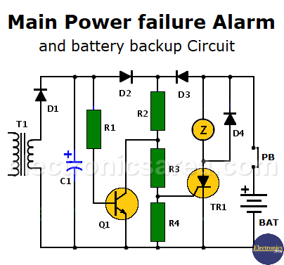
When there is no power, the voltage on the transformer secondary disappears, the transistor Q1 is placed in the cutoff region. The diode D2 is off and prevents the transistor to enter the saturation region with the battery power. The battery forward biases diode D3 and a current flows through R2, R3 and R4 resistors.
When the voltage level on the gate of the thyristor rises and TR1 becomes conductive. The current through the thyristor activates the buzzer that notifies the absence of power.
When power returns, the signal error message does not disappear because the thyristor is kept in conduction even though its gate now has a low voltage level. To turn off the alarm circuit, the battery is momentarily disconnected using the NC push button (PB). This normally closed switch can be placed in series with the 9 volt battery or in series with the thyristor.
Note: the buzzer may be replaced by a relay, a visual warning, or both.
You may also like the Power Failure alarm using transformer and relay circuit
List of components for the Main Power failure alarm circuit
- 1 x 12K resistor (R1)
- 1 x 2.7K resistor (R2)
- 2 x 1K resistors (R3, R4)
- 1 x 2N3704 (NTE85) PNP transistor
- 1 x 470uF electrolytic capacitor / 18 volts or more
- 4 x 1N4001 semiconductor diodes (D1, D2, D3, D4)
- 1 x C106Y1 (NTE5452) thyristor (TR1)
- 1 x 120/240 VAC to 9 VAC or more, 500mA transformer (T1)
- 1 x NC (normally close) Push button (PB)
- 1 x 6 or 9 volts buzzer
- 1 x 9-volt battery (BAT).