Home / Circuits / Power Supply /
12V Power Supply using Zener and 741
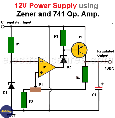
This 12V power supply has the characteristic of having a very low output impedance. This is a highly desired characteristic on power supplies and is achieved thanks to the large open loop gain of the op. amp.
The Zener diode D1 is used as a voltage reference and a PNP transistor (Q1) is used to regulate the output voltage.
To achieve stability of the output voltage, it is fed back to the non-inverting input of the operational amplifier, through resistor R4. Potentiometer P1 is used for fine adjustment of the source output to 12VDC.
12V Voltage Source Circuit Operation
The inverting input of the operational amplifier is maintained at 5.1 V by means of the zener diode (D1). If the output voltage of the power supply drops, the voltage at the op-amp’s non-inverting terminal also drops, as well as the op-amp output.
This causes transistor Q1 to conduct and raise the regulator’s voltage output, so the voltage output is stabilized.
The zener diode D2 has also been included so that the regulated output of the operational amplifier can work approximately 7 V below the unregulated input.
In this way, the regulated output is maintained until the PNP transistor saturates. This means that the unregulated input can drop below (within approximately 200 mV) the regulated output.
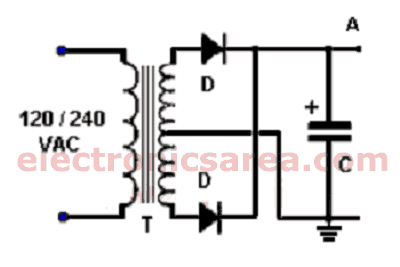
The output of the unregulated source (A) can be between 30 and 12.2 V. In this design, the output is at approximately 18 V.
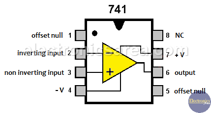
741 Operational Amplifier Pinout
Note: The unregulated output (see point A in the second diagram) connects to the unregulated input in the first diagram.
List of components of the 12 Volt Power Supply
- 1 741 operational amplifier (U1)
- 1 PNP transistor (Q1)
- 2 5.1V zener diode (D1, D2)
- 3 4.7k resistors (R1, R2, R3)
- 1 6.8k resistor (R4)
- 1 1k potentiometer (P1)
- 1 10uF (microfarad), electrolytic capacitor (C1)
- 1 240/120 VAC to 24 VAC transformer with central tap and 1.5 A (T)
- 1 2200uF electrolytic capacitor, 50 V or more (C)
- 2 rectifier diodes 1N5400 or similar (D)
More Power Supply Circuits
- 9V Power Supply circuit (Zener and Transistor)
- 12V Power Supply Circuit (1A)
- Op-Amp–Based 12V Power Supply (Zener and 741)
- 12 volt Power Supply using 7805 regulator
- 15V Power ON delay circuit
- 12 volt to 5 volt Converter Circuit
- 12V to -12V converter circuit using 555
- 12V to 9V Converter Circuit Diagram (PCB)
- 12V to 24V Converter Circuit
- 4 Amp Variable Power Supply Using the LM317
- LM317 4A Variable Power Supply (3 LM317 IC)
- LM350 Voltage Regulator circuit (Variable Power Supply)
- 20A Variable Power Supply (LM317)
- LM338 variable Voltage Regulator (5A)
- Mini variable Power supply circuit (0-30V, 1A)
- 7805 variable voltage regulator circuit (7805 and 741)
- Dual polarity Variable Power Supply (+15V / -15V) max
- Voltage Spike protection Circuit (Voltage Delay Circuit)
- Voltage Regulator circuit (Transistor - Zener)
- Power Supply Dummy load
- Joule Thief Circuit with no Toroid Coil
- 12V to 120 / 220 VAC inverter for fluorescent lamps


