Home / Circuits / Power Supply /
9VDC Power Supply using Zener and Transistor
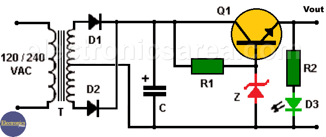
This 9VDC power supply uses a zener diode and a pass-trough transistor, can be used to power small circuits or electronic devices that would normally use a 9 volt battery, saving us the cost of a 9 volts battery while being used at home.
To better understand the operation of this 9VDC voltage source, it is recommended to first read the following tutorial: Zener diode voltage regulator, which explains the operation and design of a regulated voltage source that only uses a zener diode.
This 9VDC voltage source is very simple and can be assembled in very little space.
How the 9VDC Power supply works?
The main components of this circuit are a zener diode, which is used as a voltage reference, and a bipolar transistor to amplify the current that is delivered to the load. The transformer and rectifier diodes allow an unregulated voltage to be obtained at the electrolytic capacitor terminals of approximately 16.5 volts.
9VDC Power Supply using Zener and Transistor
With a 10 volt zener diode (Z) connected to the base of the transistor, an output voltage of 9.4 / 9.3 volts is obtained at the emitter of the transistor: Vout = Vz – Vbe = 10V – 0.6V = 9.4 VDC, where Vbe is the base – emiter voltage of the bipolar transistor. (0.6 to 0.7 volts)
A LED (D3) is included as indication that the power is ON. Although the transistor used in this circuit allows a maximum current of 1 ampere, it is recommended that the current is not greater than 500 mA.
List of the 9VDC Power Supply components
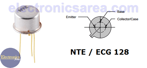
- 1 NTE128 NPN or similar transistor (Q1)
- 1 10V, 1/2 watt zener diode (Z)
- 2 1N4001 or similar diodes (D1, D2)
- 1 red or green LED (D3)
- 1 150 ohm resistor, 1/2W (R1)
- 1 680 ohm resistor, 1/4W (R2)
- 1 2200uF / 25V electrolytic capacitor (C)
- 1 120/240VAC to 24VAC center tapped transformer, 500mA (18V transformer can be used with no problems) (T1)
You may also like:
More Power Supply Circuits
- 9V Power Supply circuit (Zener and Transistor)
- 12V Power Supply Circuit (1A)
- Op-Amp–Based 12V Power Supply (Zener and 741)
- 12 volt Power Supply using 7805 regulator
- 15V Power ON delay circuit
- 12 volt to 5 volt Converter Circuit
- 12V to -12V converter circuit using 555
- 12V to 9V Converter Circuit Diagram (PCB)
- 12V to 24V Converter Circuit
- 4 Amp Variable Power Supply Using the LM317
- LM317 4A Variable Power Supply (3 LM317 IC)
- LM350 Voltage Regulator circuit (Variable Power Supply)
- 20A Variable Power Supply (LM317)
- LM338 variable Voltage Regulator (5A)
- Mini variable Power supply circuit (0-30V, 1A)
- 7805 variable voltage regulator circuit (7805 and 741)
- Dual polarity Variable Power Supply (+15V / -15V) max
- Voltage Spike protection Circuit (Voltage Delay Circuit)
- Voltage Regulator circuit (Transistor - Zener)
- Power Supply Dummy load
- Joule Thief Circuit with no Toroid Coil
- 12V to 120 / 220 VAC inverter for fluorescent lamps


