Home / Circuits / DIY Test & measuring /
How to build a logic probe using only two transistors
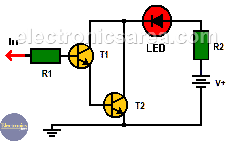
This logic probe using two transistors is a very simple circuit that can be implemented using two NPN bipolar transistors (T1, T2) in a Darlington configuration. This circuit will turn on the LED when there is a logical “1” on its input and turn it off when there is a logical “0.”
The voltage source and the high impedance of the circuit
A 5-volt voltage source is used, but it can be the same voltage source that feeds the logic circuit under test.
The logic probe will require very little current from the circuit under test due to the 1 megohm resistor (R1) in series with the tip and the high impedance of the two transistors in Darlington connection.
The use of a Darlington configuration allows a small input current to turn on the LED with no problem. Beta (b) of the 2N2222a transistor is at least 100, which means that the two transistors in the Darlington configuration will have a gain of 100 x 100 = 10,000 minimum.
Logic probe with two-transistor printed circuit board (PCB)
This circuit, due to its few elements, can be implemented in an elongated printed circuit board in the form of a pen for easy use. The following images show a suggested circuit board to implement this logic probe and a diagram with an estimated appearance of the final result.
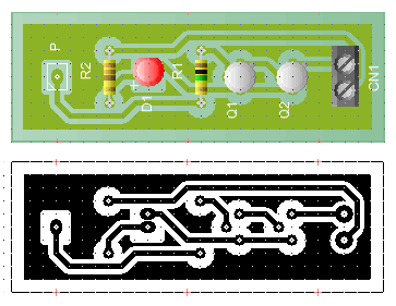
The printed circuit board must be fitted with a metallic tip connected to point P to serve as a test lead.
The power cables are connected to the CN1 terminal of the printed circuit board. Each of them (one red for the positive terminal and one black for the negative terminal) has a crocodile clip to connect the power source of the circuit under test or to connect an external voltage source.
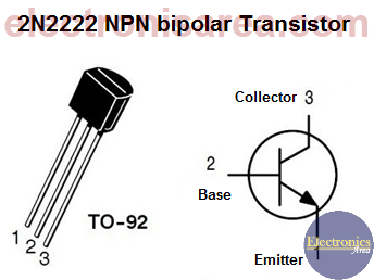
2N2222 NPN bipolar transistor pinout
Logic Probe list of components
- 2 x 2n2222a NPN transistors (T1, T2)
- 1 x 1 Megohm resistor (R1)
- 1 x 470 ohms resistor (R2)
- 1 red LED
- 1 PCB
More DIY Test & Measurement Circuits
- How do I test a Zener diode? – A simple method
- Diode tester circuit with 741
- Audible continuity tester
- Continuity tester using 741 IC
- 555 Timer tester circuit
- Op Amp Tester circuit diagram
- How to protect the 500mA fuse of a multimeter?
- How to make a current flow indicator?
- How to measure Beta of a transistor?
- Logic Probe using NOT gates
- Acoustic Logic Probe using the 555 Timer
- Logic Probe with 7 segment display
- Logic Probe circuit using CD4001 IC
- Logic Probe using two transistors


")