Home / Circuits / DIY Test & measuring /
Why use an audible logic probe?
Many logic probes use LEDs to visually indicate the logic state of a specific test point. This requires the user to look at the test point and the LED at the same time.
This could result in possible measurement errors and even damage to the device under test due to inadvertent movement of the logic probe.
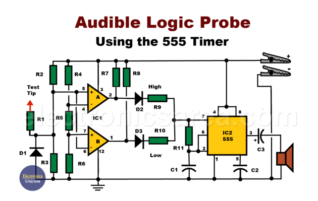
The Audible Logic Probe shown here solves this problem by using an audible prompt. A high frequency beep sounds when the sensed voltage level is high, and a low frequency beep sounds when the sensed voltage level is low. If there is a pulse train, the signal heard will be intermittent high and low frequency.
This audible logic probe can be used with both TTL and MOS circuits. The operating voltage of the circuit is 4 to 15V, depending on the circuit being tested. Current consumption is approximately 10mA for a 5V circuit and 35mA for a 15V circuit.
How does the Acoustic Logic Probe with 555 Circuit work?
Two comparators, from a chip with four, are used to sense the high and low voltage levels at the input. A voltage divider provides the necessary voltage references. (R4, R5, R6)
1 – In the low level detector IC1A. When the voltage at pin 5 of IC1 is greater than the reference voltage at pin 4, the output of this comparator goes high. This forward biases diode D2.
When this happens, resistors R7, R9 and the 555 IC produce a tone of approximately 3.5kHz. This tone is the logic high level signal.
2 – In the low level detector IC1B. When the voltage at pin 6 is less than the reference voltage at pin 7, the output at pin 1 of the LM339 IC goes high. This forward biases diode D3.
Diode D3, together with resistors R8 and R10, causes the 555 timer, configured as a stable multivibrator, to start operating.
Since this resistor combination (R8 and R10) is larger than the resistors R7 and R9, the oscillation frequency is about 300 Hertz. This signal is the logic low level tone.
The voltage divider network R2 and R3 maintain the quiescent state at approximately 1 V on the test probe when it is not connected to any signal. This way, no comparator will cause the 555 timer to produce a tone.
Input voltage levels
- In TTL technology, a low level is typically specified at 0.8 V and a high level at 2 V.
- In MOS technology, the voltage levels are typically specified as 1.5V for low level and 3.5V for high level.
Audible Logic Probe Circuit Operation
Because our Acoustic Logic Probe is powered by the circuit under test, the ground clip is connected to the circuit ground and the positive clip is connected to the positive of the circuit. When the probe is not in use, no sound is heard from the speaker.
- When the test probe is connected to the positive terminal of the circuit, the speaker emits a tone at a frequency of approximately, 3500 Hertz.
- When the probe is connected to ground, the speaker emits a tone of approximately 300 Hertz.
- When the probe detects a pulse train, it produces an audible signal of approximately 10kHz.
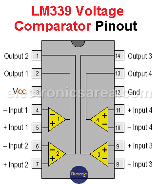
LM339 – Internal Configuration and Pinout
List of components
- 3 1N34a germanium diodes (D1, D2, D3)
- 1 LM339 IC (4 comparators) (IC1)
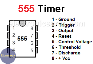
- 1 555 timer IC (IC2)
- 1 0.0 1uF disc capacitor (C1)
- 1 0.022uF disc capacitor (C2)
- 1 10uF Tantalum Capacitor (C3)
- 4 1K, 1/4 watt resistors (R1, R7, R8, R9)
- 1 220K, 1/4 watt resistor (R2)
- 1 100K, 1/4 watt resistor (R3)
- 2 22K, 1/4 watt resistors (R4, R5)
- 1 5.1K, 1/4 watt resistor (R6)
- 1 330K, 1/4 watt resistor (R10)
- 1 17K, 1/4 watt resistor (R11)
More DIY Test & Measurement Circuits
- How do I test a Zener diode? – A simple method
- Diode tester circuit with 741
- Audible continuity tester
- Continuity tester using 741 IC
- 555 Timer tester circuit
- Op Amp Tester circuit diagram
- How to protect the 500mA fuse of a multimeter?
- How to make a current flow indicator?
- How to measure Beta of a transistor?
- Logic Probe using NOT gates
- Acoustic Logic Probe using the 555 Timer
- Logic Probe with 7 segment display
- Logic Probe circuit using CD4001 IC
- Logic Probe using two transistors


