Home / Circuits / DIY Test & measuring /
Audible Continuity Tester
This audible continuity tester has been designed as an instrument that can works on live circuits. This is a very important piece of information, as continuity testers are commonly used with the circuit’s power source disconnected, like the continuity tester with an Op Amp.
The test leads have a voltage locked to (set to) at 0.3 volts when there is an open circuit, and the current is only 1 mA when there is a short circuit.
How does the continuity tester work?
The bipolar transistor Q1 forms a constant current source of 1 mA on its collector, and the test lead is fixed at a voltage of 0.3 V with a germanium diode (D2). Germanium diodes have a voltage drop of 0.3 V, when forward biased.
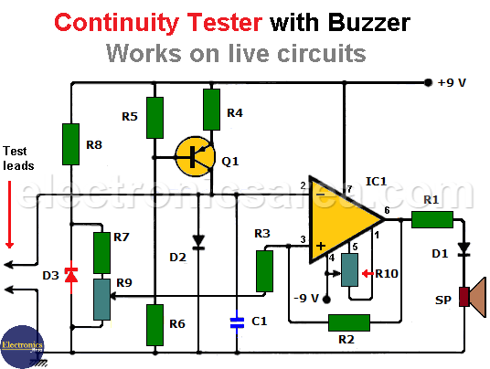
Audible continuity tester – Works on live circuits
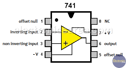
The op amp IC1 is configured as a Schmitt trigger, with an adjustable trigger voltage level via potentiometer R9.
-

- 741 op amp pinout
-

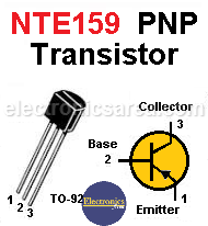
- NTE159 PNP Transistor
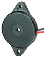
Piezoelectric Buzzer
The trigger point determines the maximum resistance with which the circuit operates, and can be preset within the range of 0 to 90 ohms.
The use of the R9 potentiometer in conjunction with the R10 potentiometer makes it easy to fine-tune the circuit for low value resistance values.
Continuity Tester Component List
- 1 741 op amp (IC1)
- 1 BC213L (NTE159) PNP bipolar transistor or similar (Q1)
- 1 5.6 V, 1 watt zener diode (D3)
- 1 1N914 silicon diode (D1)
- 1 OA47 or similar germanium diode (D2)
- 2 1 K (Kilohms) resistors (R4, R8)
- 1 1.1M (Megohms) resistor of 1.1M (R7)
- 1 2.7K resistor (R5)
- 1 12K resistor (R6)
- 1 2.2K resistor (R3)
- 1 10M resistor (R2)
- 1 resistor 47 ohm (R1)
- 1 20k potentiometer (R9)
- 1 10K potentiometer (R10)
- 1 100 nF (nanofarad) capacitor (C1)
- 1 piezoelectric speaker U5-35R or similar. (SP/buzzer)
This circuit is based on the original by R. Batty.
More DIY Test & Measurement Circuits
- How do I test a Zener diode? – A simple method
- Diode tester circuit with 741
- Audible continuity tester
- Continuity tester using 741 IC
- 555 Timer tester circuit
- Op Amp Tester circuit diagram
- How to protect the 500mA fuse of a multimeter?
- How to make a current flow indicator?
- How to measure Beta of a transistor?
- Logic Probe using NOT gates
- Acoustic Logic Probe using the 555 Timer
- Logic Probe with 7 segment display
- Logic Probe circuit using CD4001 IC
- Logic Probe using two transistors