Why use a doorbell for deaf people?
When a deaf person is alone in a house, it would be very difficult to realize that someone is knocking on the door without any visual warning signal. This circuit, a doorbell for deaf people, shows a visual warning that allows the deaf person to realize the situation in which they are.
Very important
The circuit is connected to a doorbell system that works with direct current (DC) as shown in the picture, where the actual sound signal is a buzzer. The circuit is not connected to the common alternating current (AC) doorbell system normally found in houses.
How the doorbell for deaf people circuit works?
The main component for the doorbell for the deaf people circuit is the CMOS 4001 integrated circuit, which has four two-input NOR gates. The IC1a gate, capacitor C1, and resistor R3 form an oscillator. This oscillator is enabled when the IC1b gate has a high voltage level at one of its inputs.

The “enable” signal for IC1b is a low voltage level at the junction point of capacitor C2 and resistor R2. Every time a visitor presses the momentary contact switch SW, capacitor C2 is discharged through diode D2 and resistor R1. It is at this time that the signal that enables the oscillator is obtained.
When the oscillator is running, IC1a output goes from high to low continuously for a time that depends on the values of R2 and C2. The IC1a output signal is then sent to the two inputs of each of the gates IC1C and IC1D, which are wired as two-input NAND gates.
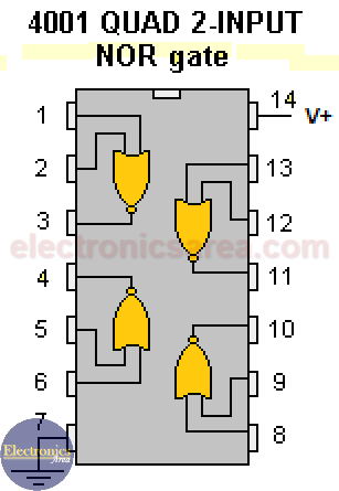
Quad 2-input NOR Gate (CD4001)
IC1C and IC1D have, at their outputs, the voltage levels that turn ON and OFF the LEDs that visually notify that a person is knocking at the door.
LEDs will blink for about 20 seconds; that means the visual signal will be active for much longer than the sound of the buzzer. If you want to increase or decrease the time of activation of the LEDs, you can change the values of R2 and C2.
You may be interested in this door opening monitor circuit
List of circuit components
- 1 x 4001B, 4 2-input NOR gates integrated circuit (IC1)
- 1 x2.7 K resistor (R1)
- 1 x 330 K resistor (R2)
- 1 x 470 K resistor (R3)
- 1 x 470 nF capacitor (C1)
- 1 x 47 uF electrolytic capacitor (C2)
- 2 x 1N4148 diodes (D1, D2)
- 6 common red LEDs (D3, D4, D5, D6, D7, D8)
- 1 buzzer (BZ)
- 1 alkaline 9-volt battery (B)
A 9-volt battery powers the doorbell for the deaf circuit. It can also operate with a supply voltage of 9 volts connected to the network (110/220VAC). This circuit has a negligible consumption when it is not active.
")

")
