Home / Circuits / DIY Test & measuring /
555 Timer Tester Circuit (PCB)
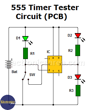
This 555 timer tester circuit, allows us to make sure that this integrated circuit works properly. This same test can be achieved by operating the 555 as an astable multivibrator, but this test does not allow observing its operation in detail. The suggested manual procedure clearly shows how the 555 IC works.
How does the 555 Timer tester circuit work?
To achieve this, it is necessary that we obtain the correct low or high voltage levels at the output of the 555 timer (pin 3), when a high or low voltage is applied to the trigger input of the 555 (pin 2).
To indicate when pin 2 is in low state and 555 was triggered, LED D1 turns on.
- When the 555 is triggered (pin 2 has “0” volts), the output (pin 3) will be high, LED D3 will turn on and LED D2 will be off.
- When the 555 is not triggered (pin 2 is Vcc (Bat)), its output (pin 3) will be low, LED D2 will turn on and LED D3 will be off.
If, for some reason, the previous steps are not met, then the 555 is damaged.
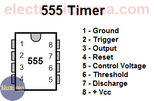
Pin 7 is not used in this circuit because its state is normally the opposite of pin 3 (the output). Pin 7 is used to discharge a capacitor that is not used in this circuit.
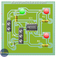
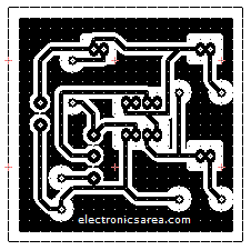
Suggested Printed Circuit Board for 555 IC Tester (PCB)
Below is a printed circuit Board (PCB) for the 555 IC tester circuit. The image on the left gives an idea of the final appearance of the PCB, and the image on the right shows the copper side of the printed circuit board.
List of components for the 555 IC tester circuit
- 1 555 IC timer (555 Timer under test) (IC)
- 1 555 base
- 3 330 ohms 1/4 watt resistors (R1, R2, R3)
- 3 LEDs, 2 red, 1 green (D1, D2, D3)
- 1 two poles switch (SW)
- 1 9-volt battery (Bat)
- 1 two terminal connector (for the battery)
- 1 three terminal connector (for the switch)
More DIY Test & Measurement Circuits
- How do I test a Zener diode? – A simple method
- Diode tester circuit with 741
- Audible continuity tester
- Continuity tester using 741 IC
- 555 Timer tester circuit
- Op Amp Tester circuit diagram
- How to protect the 500mA fuse of a multimeter?
- How to make a current flow indicator?
- How to measure Beta of a transistor?
- Logic Probe using NOT gates
- Acoustic Logic Probe using the 555 Timer
- Logic Probe with 7 segment display
- Logic Probe circuit using CD4001 IC
- Logic Probe using two transistors

")

