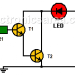
This Logic Probe is a simple circuit implemented using two NPN bipolar transistors (T1, T2) in a Darlington configuration
This Logic Probe is a simple circuit implemented using two NPN bipolar transistors (T1, T2) in a Darlington configuration
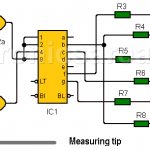
This logic probe with 7 segment display is designed with TTL technology and does not use LEDs to display the high and low logic levels found in many of the logical probes on the market. The circuit shows the capital letter “H” when there is a logical “1” or the letter “L” when there is a logical “0”.