Home / Transformers /
What is an autotransformer?
An autotransformer is a transformer where a part of the winding belongs to both the primary winding and the secondary winding of the transformer.
How does the autotransformer work?
Its operating principle is the same as the conventional transformer’s, so the relation between input and output voltages, input and output currents, and the ratio of the number of turns between the primary and the secondary winding is the same.
The currents of the primary winding and secondary winding are flowing in opposite directions, so the total current flowing through the common part of the winding is equal to the difference between the current on the low-voltage winding and the current on the high-voltage winding.
In order for an autotransformer to work properly, both windings should have the same winding sense. The transformation ratio of this transformer is close to “1”.
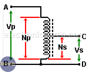
Step-down autotransformer
If an alternating voltage is applied to points A and B, and the output voltage is measured at points C and D, a lower voltage is obtained. This transformer is a step-down auto transformer. In this case, the turn ratio = Ns/Np < 1.
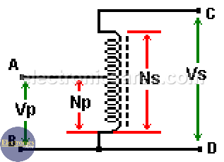
Step-up autotransformer
If an alternating voltage is applied to points C and D, and the output voltage is measured at points A and B, a higher voltage is obtained. This transformer is a step-up autotransformer. In this case, the turn ratio is Ns/Np > 1.
Advantages and disadvantages of an autotransformer
– Advantages
- Autotransformers have a lower weight and a lower cost.
- Instead of having a high-voltage winding of N1 turns, it must be provided, for low-voltage winding, with a number N2 of turns. An additional number of turns of N1 – N2.
- It must also be taken into account that the wire of the common winding section must have a copper cross-section that depends on the current difference between low-voltage winding and high-voltage winding.
- Another advantage is that there is no separation (isolation) between the primary winding and secondary winding. However, this brings the disadvantage that the primary winding is not independent of the secondary one.
- This kind of transformer can be dangerous for a person because there is a primary winding voltage between the ground connection and the common wire part of the secondary winding and primary winding. See the step-down auto transformer diagram.
– Disadvantages
- The load could be directly connected to the high voltage source if the insulation between both windings of this transformer fails.
- It has a high short-circuit current.
Applications of an autotransformer
- Soft start (reduced voltage) for squirrel cage motors to avoid high current demand at startup. Thus, at startup, it is applied from 50% to 60% of the primary voltage.
- It allows compensating the voltage drop in distribution cables in electrical installations over long distances (e.g., in rural areas)
- To interconnect transformers in 132 kV / 330 kV systems, for example.
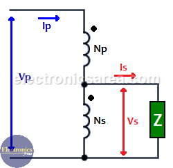
How can a conventional transformer be connected as an autotransformer?
The connection is shown in the following images, where:
- To obtain a “step-down autotransformer” using a conventional transformer, the lower terminal of the primary winding must be connected to the upper terminal of the secondary winding, and from this connection point, the output of the transformer is obtained.
- To obtain a “step-up autotransformer”, the lower terminal of the primary winding must be connected to the upper terminal of the secondary winding. The input in this case is at the junction of both windings, and the output is at the upper terminal of the primary winding.
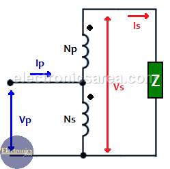
Take into account that two other possible variations of this transformer can be obtained if Np and Ns are exchanged in each of the previous diagrams.
With this type of connection, the ability to transmit power is improved, and there is also a better power factor.
More Transformer Tutorials
- Ideal Transformer Working Principle
- Transformer Turn Ratio (K)
- Impedance matching Transformer
- Autotransformer
- Transformer Structure
- Power Transformer usage
- Equivalent transformer circuits (power, audio, video and RF)
- Why is the core of a transformer laminated?
")

")

Super