Home / Circuits / DIY Test & measuring /
Continuity tester using 741 IC
This continuity tester using 741 operational amplifier, operates as a differential amplifier. A good application for this circuit would be to test welds made on a printed circuit board. It could also be used to test continuity of wires, connections, etc.
This circuit uses an LED to indicate if there is continuity or not, a different version which also uses an op amp and work on live circuits, is a continuity tester with a buzzer.
How the continuity tester works?
The voltage difference between the inverting terminal (-) and the non-inverting terminal (+) of the operational amplifier is amplified with an of open loop gain (the Op Amp do not have a feedback resistor).
The open loop gain of an op amp is very large and causes the operational amplifier output to go into saturation. This output voltage could be maximum (9 volts in our circuit) or minimum (0 V).
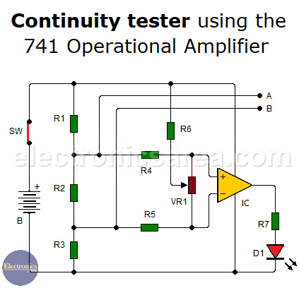
If resistors (R1, R3) and (R4, R5) have the same values, the voltage difference at the inputs of the operational amplifier is 0 volts and the output will be 0 volts.
To achieve the desired operation of the circuit, a 470 ohm resistor and a 10 kilohms potentiometer are included. This allows for a small voltage difference between the 2 inputs of the operational amplifier and causes an unbalance of the circuit.
When testing the circuit, a small resistance appears between the probes. This causes the unbalance disappears and the output of the operational amplifier turns on the LED. For testing, the circuit must not be connected to the power supply.
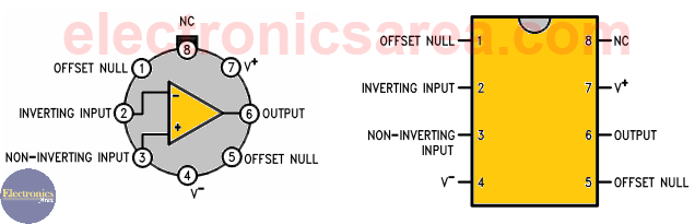
741 Operational Amplifier Pinout
Continuity tester calibration
- Connect a resistance of 4 ohms or fewer between the probes.
- Adjust the potentiometer so that the LED just lights up with the resistance that is connected between the probes.
- If we short-circuit the probes (A and B) the LED should turn off.
An Off LED indicates that there is continuity and welding or track you are testing is in good condition.
Due to the very small resistance of the tracks, connections and welds, which are tested, it is desirable that the probes (A and B) are of very good quality, very clean and have virtually no resistance.
Continuity tester using 741 list of parts
- 1 741 operational amplifier (IC)
- 2 22 K resistors (R1, R3)
- 3 1 K resistors. (R4, R5, R7)
- 1 470 K resistor. (R6)
- 1 10 ohm resistor. (R2)
- 1 10 K potentiometer. (VR1)
- 1 red LED (D1)
- 1 9 V battery (B)
- 2 probes (A, B)
- 1 NO (normally open) switch (SW)
More DIY Test & Measurement Circuits
- How do I test a Zener diode? – A simple method
- Diode tester circuit with 741
- Audible continuity tester
- Continuity tester using 741 IC
- 555 Timer tester circuit
- Op Amp Tester circuit diagram
- How to protect the 500mA fuse of a multimeter?
- How to make a current flow indicator?
- How to measure Beta of a transistor?
- Logic Probe using NOT gates
- Acoustic Logic Probe using the 555 Timer
- Logic Probe with 7 segment display
- Logic Probe circuit using CD4001 IC
- Logic Probe using two transistors


Not a bad piece to have around the bench or shop but if it were me, I’d prefer the LED to be green indicating a good connection and a to illuminate only when a connection is good. A red green dual LED would be nice to indicate red for open and green for closed circuit. Red on till circuit connection is good then switch to green. I’m going to try to make this basic circuit but add in a NPN and PNP to the output to switch the LED from Red to Green.