Home / Circuits / DIY Test & measuring /
Op Amp Tester
Many times we have an operational amplifier in our workshop or laboratory, and we do not know if it is in good or bad condition. This op amp tester lets us get out of the doubt.
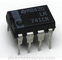
Note: This op amp tester works well for 741 Integrated Circuits (IC) and others with the same pin configuration.
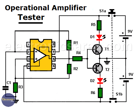
To test its operation, we will make the operational amplifier part of a simple pulse generator circuit. The alternating turn on of the 2 LEDs of the circuit indicates that it is in good condition. See the following diagram.
Operation of the Op Amp Tester
When the normally open (NO) button S1 is pressed, the op amp is powered by the two 9 volt batteries. Immediately at the output of the integrated circuit (pin 6) there is a high voltage level.
This voltage is applied to a voltage divider made up of resistors R2 and R3, and a reference voltage is set at pin 3 (non-inverting input) of the op amp.
Simultaneously, the capacitor C1 is charged through the resistor R1. The voltage across capacitor C1 eventually reaches the voltage set by the aforementioned voltage divider, with the op amp operating, at this time, as a comparator.
At this time, the op-amp output changes state from a positive to a negative output, also creating a reference voltage of opposite polarity at the non-inverting input (pin 3).
Capacitor C1 at that time begins to discharge and charge to a negative voltage, and the cycle repeats indefinitely.
When the output is high, the transistor T1 conducts and will make the LED D1 turn on. In the same way, when the output is low, the transistor T2 conducts and will make the LED D2 turn on.
The inclusion of transistors in the design is due to the possibility that some operational amplifier under test has a low output current capacity.
For the operation of the circuit, two 9V batteries or a voltage source with outputs of -9 and +9 volts are required.
Circuit component list
- 1 741 or similar op-amp (circuit under test with the same pin configuration as the 741)
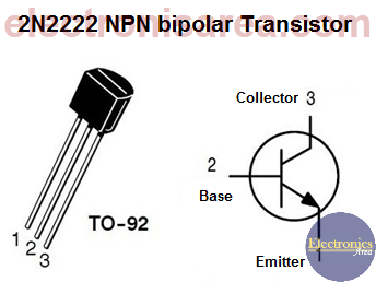
- 1 2N2222 NPN bipolar transistor (T1)
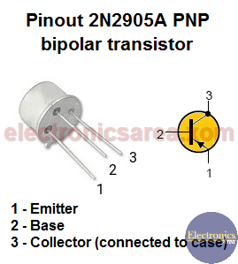
- 1 2N2905 PNP bipolar transistor (T2)
- 1 1 nF (nanofarad) capacitor (C1)
- 2 390 ohm resistors (R5, R6)
- 1 620k resistor (R1)
- 1 100k resistor (R2)
- 1 120k resistor (R3)
- 1 1k resistor (R4)
- 2 red LEDs (D1, D2)
- 1 NO (normally open) double button (S1)
More DIY Test & Measurement Circuits
- How do I test a Zener diode? – A simple method
- Diode tester circuit with 741
- Audible continuity tester
- Continuity tester using 741 IC
- 555 Timer tester circuit
- Op Amp Tester circuit diagram
- How to protect the 500mA fuse of a multimeter?
- How to make a current flow indicator?
- How to measure Beta of a transistor?
- Logic Probe using NOT gates
- Acoustic Logic Probe using the 555 Timer
- Logic Probe with 7 segment display
- Logic Probe circuit using CD4001 IC
- Logic Probe using two transistors


