What is a Logic Probe?
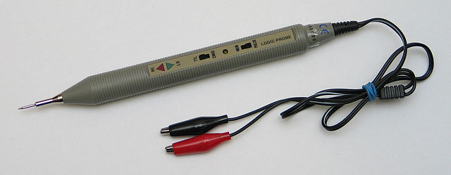
The logic probe is a simple and inexpensive instrument contained within a pen-like tube. It has 3 LED indicators that show the status of the point under test.
Logic probes are usually used to test digital circuits from the TTL or CMOS families. Many logic probes are capable of switching between testing TTL technology circuits and CMOS technology circuits using a switch.
The probe is normally powered from the circuit under test by means of 2 cables with alligator clips. A red wire connects to source voltage and a black wire connects to source negative (usually 0V or ground).
What can be done with a Logic Probe?
Logic Probes typically have 3 LED indicators that show the status of the test point.
- A logic high state (“1”) is normally shown by a red LED turning on.
- A logic low state (“0”) is normally shown by a green LED turning on.
- Digital Pulses: Some logic probes have pulse detection. When this happens, a third amber LED lights up.
- A tri-state test point (three states): Some probes also detect when the point under test does not have a defined logic state. This can happen when the circuit under test has a digital output off and there is no measurable logic level. To indicate this situation, many logic probes turn off all LEDs.
Christian Taube, CC BY-SA 2.5, via Wikimedia Commons
Advantages of a Logic Probe
- Low cost: The manufacturing cost is very low, and it is possible to make one with little effort.
- Ease of use: It is only necessary to connect the probe to the supply voltage of the circuit and then connect the test lead to the place of interest.
The most noticeable disadvantage is that the measurement is not very exact. It only shows the existence of a logical level.
Typical parameters of a Logic Probe
- A Logic 1 is measured when the TTL signal input level > 2.3 V ± 0.02, V CMOS > 70% Vdc ± 10%
- A Logic 0 is measured when TTL signal input level is < 0.08 V ± 0.02, V CMOS < 30% Vdc ± 10%
- Maximum supported supply voltage: 20 V
- Supply voltage range: 5 to 15 V
- Signal input impedance: 1 Mega-Ohm
- Input signal maximum frequency: 20 MHz
- Minimum detectable pulse width: 30 ns.
5 Logic Probe Projects for Experimentation
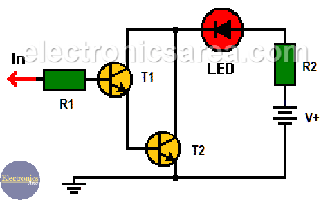
1- Logic probe with two transistors
A very simple circuit that shows the implementation of a logic probe with two NPN bipolar transistors in Darlington connection. This circuit will turn on the LED when there is a logic “1” at its input, and turn it off when there is a logic “0”. The 5 volt source used can be the same source that powers the logic circuit under test.
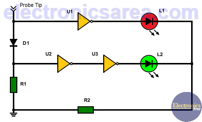
2 – Logic probe with NOT gates
This simple logic probe is made with three NOT gates, a rectifying diode, two LED, and two resistors. The logic probe allows determining the logic state of any point in a digital circuit. The signal is applied to the IN input.
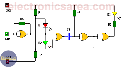
3 – How to Make a Logic probe with NOR Gates (PCB)
This logic probe is very useful for everyone who wants to have an instrument that measures the logic levels of their digital circuits. This being a circuit implemented with integrated circuits of CMOS technology, its use is recommended to test circuits that use this technology.
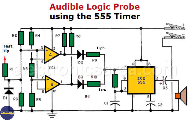
4 – Audible logic probe with 555
A reason to use an acoustic logic probe with 555: Many logic probes use LEDs to visually indicate the logic status of the point under test.
This causes the need to see the point under test and the LED at the same time. This could cause possible measurement errors and could even damage the equipment under test due to inadvertent movements of the logic probe.
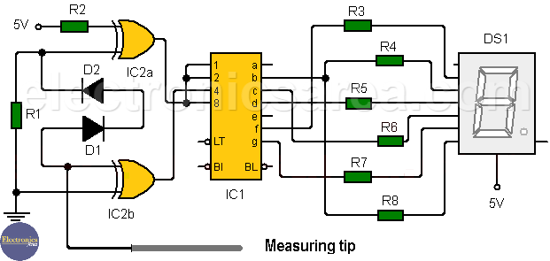
5 – Logic probe with 7-segment display
This 7-segment display logic probe is designed with TTL technology and does not use the LEDs to indicate logic high and low levels, which are found in many logic probes on the market. The circuit shows the letter H when there is a logic “1” or the letter L when there is a logic “0”.
We hope you liked all the project ideas we shared with you on this occasion. Please let us know how it turns out if you experiment with any.
More Instruments & Measurements Tutorials
- Multimeter - VOM - Tester
- Measuring resistance with an analog multimeter
- Low resistance measurement
- Measuring the resistance of sensitive components
- What is a Wheatstone bridge circuit?
- How to extend analog multimeter voltage range?
- Testing diodes and transistors with a multimeter
- What is a logic probe?
- Scientific Notation - Engineering Notation
- kWh - cost of electrical energy
- DIY circuit diagrams for test equipment


