Home / Circuits / Power Supply /
Variable voltage regulator using 7805 and 741
Usually, when we want to implement a variable voltage regulator, we use components like the LM317 voltage regulator. Since we don’t always have these components, we have to use other options. If we have a 7805 fixed voltage regulator and a 741 op amp, we can achieve the variable voltage regulator we want.
With this new variable voltage regulator design, we can get output voltages ranging from 7 to 30 volts and a current of up to 1.5 amps.
How the Variable voltage regulator works?
The LM7805 monolithic voltage regulator has 5VDC at its output if pin # 2 is grounded, but this is not the case.
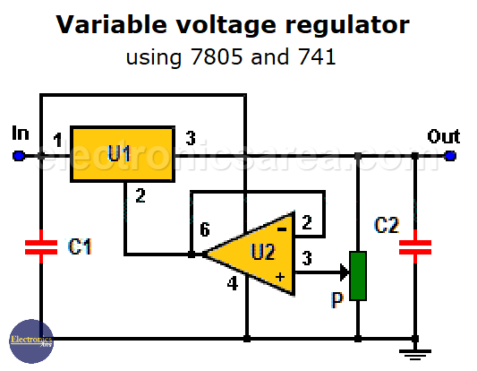
Variable voltage regulator using 7805 and 741 op amp.
Pin # 2 of the 7805 regulator has a voltage that varies according to the voltage value obtained from the 10K potentiometer (P). This voltage is applied to pin # 2 of the 7805 regulator through the op amp configured as a voltage follower.
Any increase in voltage on the potentiometer arrow implies an increase in the voltage at pin # 2 of the voltage regulator and, therefore, an equal increase in the output (Vout).
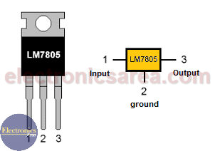
LM7805 Voltage Regulator Pinout.
For the voltage range mentioned above, the unregulated voltage applied to the Vin input must be at least 32 volts, because the voltage drops 2 volts between the input and the output of this regulator.
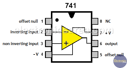
741 op amp pinout
Capacitor C1 is necessary if the voltage regulator is far from the capacitor that is part of the “unregulated voltage source” (transformer, diode bridge and capacitor, which are connected to Vin) and capacitor C2 is necessary to improve the stability and transient response of the circuit.
Component List for Variable Voltage Regulator
- 1 LM7805 (5 volts fixed) monolithic voltage regulator (U1)
- 1 LM741 op amp (U2)
- 1 10K potentiometer (P)
- 1 0.33 uF (microfarads) capacitor (C1)
- 1 0.1uF capacitor (C2)
- 1 heatsink for the lm7805 integrated circuit
Note: The unregulated voltage source (transformer, diode bridge and capacitor), that need to be connected to Vin is not included on the circuit diagram.
More Power Supply Circuits
- 9V Power Supply circuit (Zener and Transistor)
- 12V Power Supply Circuit (1A)
- Op-Amp–Based 12V Power Supply (Zener and 741)
- 12 volt Power Supply using 7805 regulator
- 15V Power ON delay circuit
- 12 volt to 5 volt Converter Circuit
- 12V to -12V converter circuit using 555
- 12V to 9V Converter Circuit Diagram (PCB)
- 12V to 24V Converter Circuit
- 4 Amp Variable Power Supply Using the LM317
- LM317 4A Variable Power Supply (3 LM317 IC)
- LM350 Voltage Regulator circuit (Variable Power Supply)
- 20A Variable Power Supply (LM317)
- LM338 variable Voltage Regulator (5A)
- Mini variable Power supply circuit (0-30V, 1A)
- 7805 variable voltage regulator circuit (7805 and 741)
- Dual polarity Variable Power Supply (+15V / -15V) max
- Voltage Spike protection Circuit (Voltage Delay Circuit)
- Voltage Regulator circuit (Transistor - Zener)
- Power Supply Dummy load
- Joule Thief Circuit with no Toroid Coil
- 12V to 120 / 220 VAC inverter for fluorescent lamps


