Home / Circuits / Power Supply /
12 volt Power Supply using the 7805 IC
This 12 volt power supply using the 7805 IC is simple and useful. Sometimes we need to get 12 VDC, but we only have 5 or 9 volts regulators (7805, 7809).
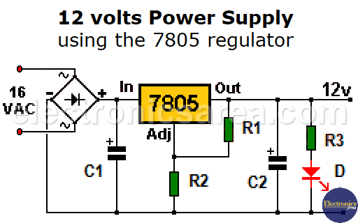
This voltage regulator looks like the fixed voltage regulator we already know, but with the difference that it have two additional resistors (R1 and R2) (see the image).
How the 12 volt Power Supply using 7805 works?
These two resistors are used to establish a voltage divider, which puts a non-zero voltage on the COMMON (ADJ) pin of the 7805 regulator.
The current that flow through the 120 ohms resistor (R1) is: IR1 = (Vout 7805 – Vadj 7805) / R1 = 5V / 120 = 41.7 mA. This current is the same that flows through the 18o ohms resistor (R2), so IR1 = IR2 = 41.7 mA.
Calculating the voltage at the COMMON pin (now ADJ) of the 7805, we get: VADJ = IR2 x R2 = 41.7 mA x 180 ohms = 7.5 V
The total output voltage is: Vout = VR2 + VR1 = 12.5V. Very close to the 12 Volts we need.
12 volt Power Supply using the 7805 regulator
If what you need is exactly 12 volts, you can replace resistor R2 with a 250 ohm potentiometer. Once the potentiometer has been adjusted so that there is exactly 12 volts at the output, it should no longer be manipulated.
From the above, it follows that the 180 ohm resistor serves to increase the voltage at the COMMON pin. If we want to get a different voltage, we just have to change the value of resistors or use a potentiometer.
Notes:
- We changed the name of the 7805 COMMON pin by the name ADJ because, the voltage on this pin can be changed using external resistors.
- The voltage between the Output pin and the ADJ pin of the regulator, must be maintained at 5 volts.
- The LM7805 integrated circuit must use a heatsink to prevent any damage.
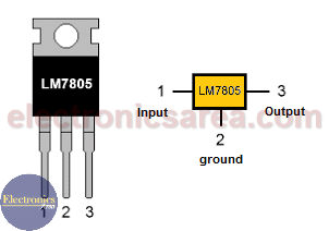
LM7805 voltage regulator Pinout
Another circuit you might be interested in, which also uses the LM7805 IC, is the Variable voltage regulator with an Op amp.
List of components for the 12 volt power supply
- 1 diode bridge (DB)
- 1 7805 IC voltage regulator
- 1 120 ohms resistor, 1/4 watt (R1)
- 1 180 ohms resistor, 1/4 watt (R2)
- 1 220 ohms resistor, 1/4 watt (R3)
- 1 250 ohms potentiometer
- 1 2200uF, (microfarads) 50 volts electrolytic capacitor (C1)
- 1 10uF, 25 volts electrolytic capacitor (C2)
- 1 red LED (D)
- 1 220/110VAC to 16VAC (not shown on the diagram) transformer to be connected to the diode bridge
- 1 heatsink for the LM7805 IC
More Power Supply Circuits
- 9V Power Supply circuit (Zener and Transistor)
- 12V Power Supply Circuit (1A)
- Op-Amp–Based 12V Power Supply (Zener and 741)
- 12 volt Power Supply using 7805 regulator
- 15V Power ON delay circuit
- 12 volt to 5 volt Converter Circuit
- 12V to -12V converter circuit using 555
- 12V to 9V Converter Circuit Diagram (PCB)
- 12V to 24V Converter Circuit
- 4 Amp Variable Power Supply Using the LM317
- LM317 4A Variable Power Supply (3 LM317 IC)
- LM350 Voltage Regulator circuit (Variable Power Supply)
- 20A Variable Power Supply (LM317)
- LM338 variable Voltage Regulator (5A)
- Mini variable Power supply circuit (0-30V, 1A)
- 7805 variable voltage regulator circuit (7805 and 741)
- Dual polarity Variable Power Supply (+15V / -15V) max
- Voltage Spike protection Circuit (Voltage Delay Circuit)
- Voltage Regulator circuit (Transistor - Zener)
- Power Supply Dummy load
- Joule Thief Circuit with no Toroid Coil
- 12V to 120 / 220 VAC inverter for fluorescent lamps


